Table of Contents
FET Characteristics and Amplifier “An electric field is used to control the flow of current through a semiconductor in a device known as a field-effect transistor”, which is also abbreviated as F.E.T. The source connection, the Gate connection, and the Drain connection are the three connections that make up a field-effect transistor (F.E.T.; sometimes JFET, MOSFET). When a voltage is applied to a FET’s Gate, the resulting change in resistance between the device’s Drain and source can be used to regulate the amount of current that flows through the FET. This allows the user to control how many current flows through the FET.
Because they require just one carrier to do their jobs, field effect transistors (F.E.T.s) are sometimes called unipolar transistors. That is to say, field effect transistors can only ever work with either electron (n-channel) or holes (p-channel) as the charge carriers, never both at the same time. This is because electrons are more minor than holes, while spots are more significant than electrons.
There is a large number of members in the field effect transistor family. Low frequencies often result in a field effect transistor having a relatively high input impedance. This is due to the high voltages required for field-effect transistors to function correctly. The most common type of field-effect transistor is known as a metal-oxide-semiconductor field-effect transistor, or MOSFET for short. These transistors are made up of metal-oxide semiconductors (metal-oxide-semiconductor field-effect transistors).
FET Characteristics and Amplifier: Uses, Working Principle, Components, Setup, Types & Price.
What are FET Characteristics and Amplifier Training Board?
“In a field-effect transistor, the flow of current in a semiconductor is controlled by employing an electric field.” The three connections that make up a field-effect transistor are the source, the Gate, and the Drain (F.E.T.; sometimes JFET, MOSFET). One can control the amount of current going through a F.E.T. by applying a voltage to its Gate, which results in a change in the resistance between the device’s Drain and source.
F.E.T.s are also considered unipolar transistors because they function with only a single carrier. That is to say, field effect transistors can only ever work with either electron (n-channel) or holes (p-channel) as the charge carriers, never both at the same time. The family of field-effect transistors is quite extensive.
A field effect transistor’s input impedance is typically reasonably high at low frequencies. This is because field effect transistors operate at very high voltages. The metal-oxide-semiconductor field-effect transistor, sometimes known as a MOSFET, is the kind of field-effect transistor used most frequently (metal-oxide-semiconductor field-effect transistor).
Uses of FET Characteristics and Amplifier Training Board
The most common field-effect transistor, or F.E.T., is called a metal-oxide-semiconductor field-effect transistor, or MOSFET for short. CMOS, a complementary metal oxide semiconductor, is the name of the manufacturing technology used for digital integrated circuits today. In this production method, a p-channel MOSFET and an n-channel MOSFET are connected in series so that when the former is turned on, the latter is rendered inoperable.
Electrons can travel through the channel in any direction when field-effect transistors (F.E.T.s) are operated in their linear mode. Most electronic devices are built symmetrically from the source to the DrainDrain, meaning that the naming convention for the drain and source terminals is pretty arbitrary.
Because of this, F.E.T.s are an excellent choice when it comes to employing them in the function of route switches for analogue signals (multiplexing). Utilizing this concept will allow one to create items such as a solid-state mixing board. As an amplifier, F.E.T. is widespread. As a result of its high input resistance and low output resistance, it can serve as a valuable buffer in some circuit configurations, such as the common-drain (source follower) design.
IGBTs are utilised in internal combustion engines because they enable for quick switching between ignition coils while blocking electricity.
Working Principle of FET Characteristics and Amplifier
The influence exerted by the Field Transistors is referred to as “Voltage” driven devices because they regulate the current that flows from the source to the Drain by adjusting the voltage given to their input terminal, which is also referred to as the Gate. An external source supplies this voltage. This is because to run the gadget, and they use the voltage delivered to them.
Field effect transistors, also known as F.E.T.s, are beneficial components for integrated circuits due to their low power consumption and compact size (I.C.s). In addition, F.E.T.s are utilized in high-power switching applications as voltage-variable resistors (V.V.R.s) in operational amplifiers (Op-Amps) and tone controls, among other things, for mixer operation on F.M. and T.V. receivers, as well as in logic circuits. In addition, F.E.T.s are utilized in logic circuits.
Components of FET Characteristics and Amplifier Training Board
A field-effect transistor (F.E.T.) has four terminals: the Source, Drain, Gate, and Body.
Source:
The term “source” refers to the terminal in the F.E.T. that most charge carriers must pass through to enter.
Drain:
Most charge carriers leave the F.E.T. through the Drain terminal, also known simply as the Drain.
Gate:
The development of the Gate, also known as the gate terminal, is the result of the diffusion of an N-type semiconductor with a P-type semiconductor. As a consequence of this, a heavily doped P.N. junction area is formed, which is accountable for regulating the flow of carriers from the source to the Drain.
Body:
This substrate, which is often referred to as the body, is where the F.E.T. is formed. It has an internal connection to the source pin, which enables its effects to be completely ignored in applications that use discrete logic. This is because these applications have this link. Because several transistors will share this pin in integrated circuits, it is typically connected to the power supply that supplies the most significant negative voltage in an NMOS circuit and the power supply that supplies the highest positive voltage in a PMOS circuit.
This is done so because this pin will be shared by multiple transistors. When the Body connection is involved, it is absolutely necessary to guarantee F.E.T. performance by paying particular attention to the design of the component and the relationship it has with other parts of the system.
Channel:
This is the part of the signal path via which most carriers travel from the source terminal to the drain terminal.
FET Characteristics and Amplifier Training Board Setup
In the current scenario, the V.G.S. of a JFET may be precisely regulated thanks to the usage of a D.C. supply as the biasing source for the JFET. This is made possible by the utilisation of a D.C. supply as the biasing source. The use of a D.C. supply is what makes this accomplishment tenable. By adjusting the value of the V.G.S., we are able to modify the voltage that is applied between the Drain terminal and the Source terminal, which in turn provides us with a greater degree of control over the output of the circuit.
Altering the value of the V.G.S. to achieve this objective is one possible course of action. We are now able to plot the I-V characteristics curve of a JFET because we have access to all of this relevant information.
The output characteristics of a JFET are drawn between the drain current (I.D.) and the drain-source voltage (V.D.S.), while the gate-source voltage (V.G.S.) remains unaltered, as illustrated in the graphic that follows. These characteristics are drawn between the drain current and the drain-source voltage. This is carried out with the gate-source voltage (V.G.S.) maintained in a steady state.
Region de Limitation –
Within this portion of the circuit, the JFET is disabled, meaning that the Drain does not receive any current. The ID will instead make its way backwards, from the Drain to the source.
It’s called the Ohmic Region.
The drain current, designated by I.D., that is beginning to flow from the Drain to the source, starts to meet some resistance from the JFET during this period. In this region, you can find the middle of a JFET. The amount of current moving through the JFET has a direct and proportional relationship with the voltage being applied to the circuit.
Saturation Region –
When the drain-source voltage reaches a value such that the current flowing through the device remains constant with the drain-source voltage and only varies with the gate-source voltage, the device is said to be in the saturation region. Saturation occurs when the drain-source voltage reaches a value that is high enough. This happens when the voltage across the Drain and source goes a matter that is no longer affected by the voltage across the Gate and source.
The area where the structure fails —
The depletion region will fail, the JFET will lose its capacity to resist current, and the drain current will continue to build up indefinitely if the voltage from the Drain to the source, denoted by V.D.S., is higher than the maximum threshold value.
Types of FET Characteristics and Amplifier Training Board
Three main categories can be used to classify F.E.T. amplifiers, each determined by the terminal that serves as the standard input and output. (This is comparable to an amplifier that uses a BJT, which stands for bipolar junction transistor.)
Amplifier with a standard gate: The Gate has a connection that is shared by both the input and the output.
Common source amplifier: The source is shared by the input as well as the output.
Common drain amplifier: The brain drain is something that the input and output share in common. In some circles, it is called a “source follower.”
FET Characteristics and Amplifier Training Board Brochure
The channel will open to pass electrons when no voltage is applied across the gate terminal. As a result, the drain terminal is where most of the current is received. The size of the flow of a draft is determined by the internal resistance of the channel as well as the potential difference between the drain terminals and the source terminals.
When the gate terminal is negatively biased regarding the source terminal, the P-N junction that is created, on the other hand, has the opposite effect. Because the channel is becoming more constricted, a depletion region is developing, which increases the channel’s resistance. This results in a reduction in the quantity of current flowing between the source and the DrainDrain a consequence.
FET Characteristics and Amplifier Training Board Price
You can purchase an Analog F.E.T. Characteristics Apparatus for Education Lab Trainer in Ambala for Rs 3499.
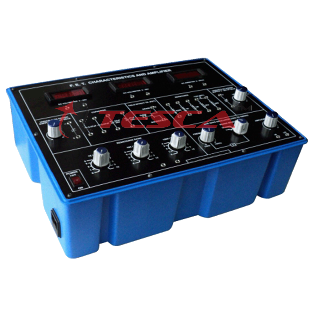
TescaGlobal FET Characteristics and Amplifier Training Board
The FET Amplifier Research Training Experimental Board was established to accomplish this specific goal.
Students studying in the fields of science and engineering can gain a significant amount of knowledge from the experience gained from working with these boards.
Object:
- FET Amplifier Research:
- Because of this, it is necessary to plan and compute the finite gain of a FETAmplifier.
- To provide a visual representation of the properties of overloading.
- Consequently, I am attempting to graph the frequency response.
- To provide a measure of the total amount of input resistance.
- It is essential to determine the output’s impedance.
Features:
The board comprises the following built-in pieces :
The +15V D.C. at 50mA output from the built-in IC-regulated Power Supply is available.
The term “transistor” refers to a field effect and is a noun.
Power in and power out, a fuse, and a gleaming light fixture are shown here.
A sufficient quantity of electronic components besides those already mentioned. An adequate amount of patch cords with stackable rear 4-mm spring-loaded plugs and a total length of fifty centimeters are required. Terminals, high-quality sockets, and reliability are provided at the correct positions on the panel for making connections and observing waveforms.
* The instructions give a solid basis by describing the object, theorizing its function, describing how to develop a prototype that works, recommending reports that should be produced, and referring texts pertinent to the situation.
* This package has a total mass of three kilograms (Approx.)
Size: 340W 110H 210D
Equipment That Is Necessary for Addition:
The instruments are included: an Audio Frequency Generator; an A.C. Millivolt meter; a Decade Resistance Box; and a 20MHz Cathode Ray Oscilloscope.


Add comment