
Electricity Lab
Order Code: 23246880.2
Category: General Lab Equipment II
Technical Specifications: (Ref. No.: 23-24/6880) ''Brand: To be mentioned by the Bidder, Model: To be mentioned by the Bidder,Place of Origin: To be mentioned by the Bidder, Country of Manufacturer: To be mentioned by the Bidder ...
SPECIFICATION
Technical Specifications: (Ref. No.: 23-24/6880)
''Brand: To be mentioned by the Bidder, Model: To be mentioned by the Bidder,Place of Origin: To be mentioned by the Bidder, Country of Manufacturer: To be mentioned by the Bidder
Feature:
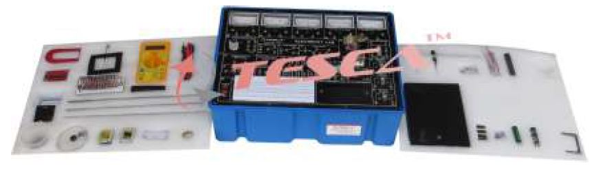
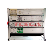
Basic Electrical Circuit Lab is ideal for electrical, mechanical, automotive, science, civil & electronics engineering learning. All the necessary equipment for electric circuit experiments such as power supply, function generator; analog and digital meters are installed on the main unit for the requirement of experiment. The whole essential topics of electrical circuit learning are studied by different modules.
SPECIFICATIONS:
1. DC POWER SUPPLY
(1) Fixed DC power supply:,a. Voltage range: +/-5V?+/-12V b. Max. Current output: 0.3A c. With output over-load protection
(2) Dual DC power supply:
a. Voltage range?+/-3V~ +/-18V, continuously adjustable, b. Max. Current output: 1A,c. With output over-load protection
2. AC POWER SUPPLY
a. Voltage range: 9V~0V~9V,b. Max. Current output: 500 m A, c. With output over-load protection
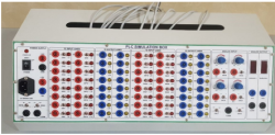
3. SINGAL GENERATOR
(1) Pulse generator: (TTL level)
a. Frequency range: 1Hz~10KHz / 4 settings, continuously adjustable, b. Fan out: 10 TTL load
(2) Pulse switches:
a. 2 independent output, TTL level, b. With Q, Q output,pulse width > 5ms, c. Fan out: 10 TTL load
(3) Data switches
a. 8 sets independent control output,TTL level with De-bounce circuit.,b. Fan out: 10 TTL load
4. FUNCTION GENERATOR
(1) Output waveform: Sine, triangle, square, (2) Output frequency: 10~100KHz/4 settings, continuously adjustable
(3) Output amplitude: 18Vpp (open circuit) 9Vpp (50 O load)
5. TESTING AND DISPLAY
(1) 3 1/2 digital voltmeter/ammeter
a. DC voltage range: 2V?200V, b. DC voltage accuracy: +/-(0.3% of reading +1 digit),c. DC current range: 200
(2) Galvanometer
a. Current range 50mA, b. Accuracy Class 2.5,(3) LED indicator
a. 10 sets independent LED indicates high, low logic state, b. Input impedance: ≥100KΩ
(4) Digital display
a. 2 sets independent 7-segment LED,b. With BCD-7segment decoder/driver and DP Input c. Input with 8-4-2-1 code
Breadboard: 1680 tie-point breadboard on top panel can be easily put into and taken off
Accessories: Experiment manual, connection leads, connection plugs, breadboard
List of Module:
a. Basic Device Module,b. Basic Electricity Experiment Module,c. Sensor Module(1),d. Sensor Module(2)
e. Diode, Clipper and Clamper Module
f. Rectifier, Differentiator Integrator Circuit Module
g. Transistor Amplifier Circuit Module
h. Multi-Stage Amplifier Circuit Module
i. FET Circuit Experiment Module
j. OP Amplifier Circuit Module 1, 2, 3, 4, 5
k. Combination Logic Circuit Experiment Module 1, 2, 3, 4, 5
l. Sequential Logic Circuit Experiment Module 1, 2
j. Load Unit Module
Basic Electrical/Electronic Circuit Lab with all Module and Complete teaching manual and advanced learning course
ListofExperiments:
A)Basic Electricity Experiments
1.Basicelectricity
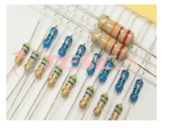
(1)Resistor measurement (2)DC voltage/current measurement (3)Ohm'slaw (4)AC voltage/current measurement (5)Series/parallel circuit
(6)Wheatstone bridge (7)Kirchoff'slaw (8)Thevenin'stheorem (9)Norton'stheorem (10)Maximum power transfer theorem (11)DC RC and RL transient phenomena (12)Power in DC circuit (13)AC current/voltage experiment (14)AC RLC series/parallel circuit (15)Resonant circuit (16)Power in AC circuit
2.Controlcircuit
(1)Water level control (2)Metal detector (3)Light controller
(B)Electronic Circuit Experiments
1.Diode experiments
(1)The Diode V-I characteristic curves (2)The series diode clipping circuit (3)The series diode clipping with bias circuit(4)The parallel diode clipping circuit(5)The parallel diode clipping with bias circuit (6)The diode clamping circuit (7)The diode clamping circuit with bias (8)LED current characteristics (9)Diode rectifier circuit(10)Filter circuit (11)Voltage multiplier
2.Transistorexperiment
(1)MeasuringI,I,I and of PNP transistor (2)Measuring I,I,I and of NPN transistor (3)Transistor output characteristic scurve EBC EBC β β 3.Transistor amplifier (1 )Fixed bias circuit (2)Divide bias circuit (3)Feedback bias circuit (4)Common emitter transistor amplifier
(5)Common-collector transistor amplifier (6)Common base transistor amplifier
4.Multistage amplifier
(1)RC-coupled amplifier (2) Direct-coupled amplifier (3)Transformer-coupled amplifier (4)Push-pull amplification circuit
5.Darlington and FET circuit
(1)Darlington's circuit (2)Field Effect Transistor (FET)type and characteristics (3)JFET type and characteristics (4) MOSFET type and characteristics (5)Common source amplifier (6)Common drain amplifier (7)Common gate amplifier
6.OP amplifiers
(1) OP amplifier characteristics (2) Non inverting amplifier (3)Inverting amplifier (4)Voltage follower circuit (5)Adder circuit 6)Differential amplifier (7)Clipping circuit (8) Constant-voltage circuit (9)Constant-current circuit (10)Differentiator circuit (11)Integrator circuit (12)Instrumentation amplifier
(4)RC phase-shift oscillator (5)Wien osc
Enquiry Form
Related Product


Tesca specialize in doing turnkey projects that is fully operable when it is handed over to the project authority. Starting from inception to application training, Tesca provides the services as ONE source solution. Working side by side with government authorities and people across the World, we help countries to perform better. We support countries grow their economies, strengthen their education and health systems and improve financial management. We do this by providing consultancy & training in environment safety, education, health strengthening.
Category
Useful Links
Contact Us
International Sales:
export@tesca.in
 91-9829132777
91-9413330765
India Sales:
indiasales@tesca.in
91-9588842361
2026 © All Rights Reserved.