
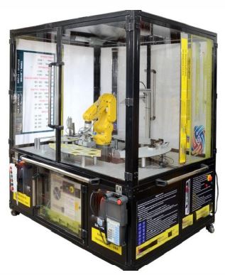
6-Axis Robotic Training System
SPECIFICATION
6-Axis Robotic Training System
- An ideal desktop 6-axis Robotic robot arm trainer for AI engineering learners
- It an open platform hardware product
- It provided with the multi-functional extension module which expand the external interface of the robot
- Designed with six degrees of freedom
- Its end-effectors perform 3D omnidirectional movement which allow tilt and turn, same as the typical industrial robot
- It have a 0.2mm repeatability and achieve high precision through stepping motors with multistage gearbox
- The body design follow the safety principle which is curved and have safety position restrictions to prevent pinching
- Supplied as professional kit configuration
Technical Specifications:
- Axle number: 6+1 or better
- Maximum Payload: 400g or higher
- Working Radius: 310 ~ 320 mm
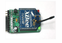
- Communication Interface: USB / WiFi / Bluetooth / RS485 or more
- Base Diameter: Minimum 155mm
- Repeated Positioning Accuracy: 0.2mm or better
- Power: 12V / 4A DC, 50W
- Axis Motion Parameters (160g Payload):
- Axis 1: -100? ~ +100?, Maximum Speed 31?/s
- Axis 2: -60? ~ +90?, Maximum Speed 65?/s
- Axis 3: -180? ~ +50?, Maximum Speed 28?/s
- Axis 4: -180? ~ +180?, Maximum Speed 110?/s
- Axis 5: -180? ~ +50?, Maximum Speed 33?/s
- Axis 6: -180? ~ +180?, Maximum Speed 66?/s
- Pen Holder (dia.): 10 ~ 15mm
- Suction Cup Parameters (cup dia.): 10 ~ 12mm
- Gripper Parameters (opening size): 27mm or higher
- 3-Finger Soft Gripper (opening size): 27mm or higher
- Software: Studio, GRBLcontroller3.6 and Blockly & Scratch Graphic Programming
The following items included in the Professional Kit -
- Robot arm X 1
- Power supply and High-speed USB cable
- IDC cable X 1 and Pen holding X 1
- Micro servo gripper module X 1
- Pneumatic set (Including pneumatic box, suction cup, two-finger gripper, three-finger soft gripper) X 1
- Multifunctional box (Extension Module) X 1
- Sticker X 1 and Handbook X 1
- Robot controller X 1
- Printer operation manual X 1 supplied with Control Simulation Software of below features & specifications as standard:
Features & Specifications:
- Software combine controller design & implementation into one logical process
- This reduce learning difficulties and help quickly to understand & create a working control system
- User can use the software icons and wire them together on screen, just as they would draw a control system on a piece of paper
- The icons include important parts of controllers, signal generators, manually controlled signals & voltages and virtual instruments
- The software can be used to record important variables
- Plotting the results in a chart and exporting data for use in other programs
- Students can create one or more types of controller and simulate the theoretical responses
- The developer UKAS management system certified and mentioned in ISO certificate that has to be submitted
- The user guide show users how to use the software and how to build and test common control systems, such as:
- Design and implementation of three-term controllers
- Design of controllers and filters
- Simulated signals: Signal generator (sinusoidal, saw tooth & square wave), with variable frequency, amplitude & offset and D.C. level (fully variable)
- Virtual instruments: Digital meter, Bar graph, Analogue meter, Oscilloscope and Chart recorder
- Controller blocks: Proportional gain, Integral gain, Derivative gain and Phase advance
- Simulation blocks: Integer, First order system, Double integrator, Second order system, First order with integrator system and Second order under damped system
- Other blocks: Gain, Voltage to frequency convertor, Delay, Discrete transfer, Saturation, Summing junction (three input), Multiplier (three input), Switch and Relay
- Fuzzy logic blocks: Fuzzy Pot, Fuzzifier, Defuzzifier, Fuzzy Multiplexer & Demultiplexer, Fuzzy AND, OR & NOT, Fuzzy AND Table, Fuzzy Combined Meter and Fuzzy Single Meter
- Developed in accordance with the latest European Union directives
- Single user licensed version with dongle included
Enquiry Form
Related Product


Tesca specialize in doing turnkey projects that is fully operable when it is handed over to the project authority. Starting from inception to application training, Tesca provides the services as ONE source solution. Working side by side with government authorities and people across the World, we help countries to perform better. We support countries grow their economies, strengthen their education and health systems and improve financial management. We do this by providing consultancy & training in environment safety, education, health strengthening.
Category
Useful Links
Contact Us
International Sales:
 91-9829132777
91-9413330765
India Sales:
91-9588842361
2026 © All Rights Reserved.