
Bending Of Beam - Uniaxial
Order Code: 32164
Category: Strength of Materials Lab
Features Symmetrical and unsymmetrical bending on a beam Symmetrical and unsymmetrical cross-sectional profiles: I, L and U Combined bending and torsion loading by way of eccentric force application Bending of a beam symmetrically - also known as...
SPECIFICATION
Features
Symmetrical and unsymmetrical bending on a beam
Symmetrical and unsymmetrical cross-sectional profiles: I, L and U
Combined bending and torsion loading by way of eccentric force application
Bending of a beam symmetrically - also known as uniaxial bending - occurs when the load plane coincides with one of the main axes of the beam cross-section. The beam then deflects in the direction of the load and can be described by elastic lines.
In unsymmetrical bending of a beam - also known as complex or biaxial bending - the main axes of the cross-section do not coincide with the direction of loading. To prevent torsion, the line of application of the load must pass through the shear centre. If it does not, the beam undergoes combined bending and torsion loading.
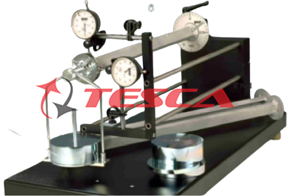
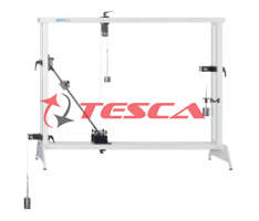
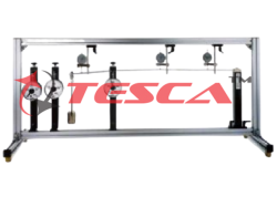
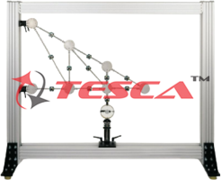
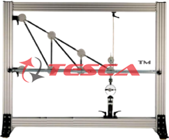
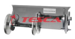
Tesca Bending of Beams: Uniaxial or Unsymmetrical is used to perform experiments relating to symmetrical and unsymmetrical bending and to combined bending and torsion loading. The beam under investigation is clamped into place on one end and loaded down by a set of weights at the free end. Two dial gauges record the horizontal and vertical deformation of the beam. The unit includes three beams with different cross-sectional profiles: I, L and U. The beam can be clamped with freedom to rotate in any direction. This enables investigation of loading along the main axis or of the general load case. An angle scale at the clamping point indicates the angular position of the beam. It is possible to adjust the load application point eccentrically, so that purely unsymmetrical bending or combined bending and torsion loading is investigated.
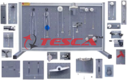
The various elements of the experiment are clearly laid-out and housed securely in a storage system. The well-structured instructional material sets out the fundamentals and provides a step-by-step guide through the experiments.
Specifications
Experimental unit for general and unsymmetrical bending of straight beams
3 beams: I, L and U profiles
Clamping flange of beam can be clamped in the pillar free to rotate in any direction
Clamping flange with angle scale to indicate the angular position of the beam
Eccentricity of load application point adjustable
2 dial gauges with bracket to record the horizontal and vertical deformation of the beam under load
Storage system to house the components
Technical Specifications
Aluminum beam
Deformed length: 500mm
The eccentricity of load application point: 0...25mm
Dial gauges
0...10mm, graduations: 0,01mm
Angle scale
- 0...360°, graduations: 1°
Weights set
1x 2,5N (hanger)
- 1x 2,5N
3x 5N
Experiment Possibilities
Product moment of inertia (Iyz) and 2nd moment of inertia (Iy, Iz)
Euler/Bernoulli equation
Symmetrical bending on a beam (uniaxial)
With I-profile
With L-profile
With U-profile
Unsymmetrical bending (complex) on a beam with an L-profile
Calculation of the neutral fibres
Combined bending and torsion loading by way of eccentric force application
Determination of the shear centre on a beam with a U-profile
Familiarization with shear flow (shear forces in a cross-section)
Comparison of calculated and measured values
Scope of Delivery
1 experimental unit
3 beams
2 dial gauges with bracket
1 set of weights
1 spirit level
1 hexagon socket wrench
1 storage system with foam inlay
1 set of instructional material
Enquiry Form
Related Product
Tesca specialize in doing turnkey projects that is fully operable when it is handed over to the project authority. Starting from inception to application training, Tesca provides the services as ONE source solution. Working side by side with government authorities and people across the World, we help countries to perform better. We support countries grow their economies, strengthen their education and health systems and improve financial management. We do this by providing consultancy & training in environment safety, education, health strengthening.
Category
Useful Links
Contact Us
International Sales:
 91-9829132777
91-9413330765
India Sales:
91-9588842361
2026 © All Rights Reserved.