
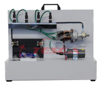
Car Electric Actuator Trainer
Order Code: 32541
Category: Automotive Trainers
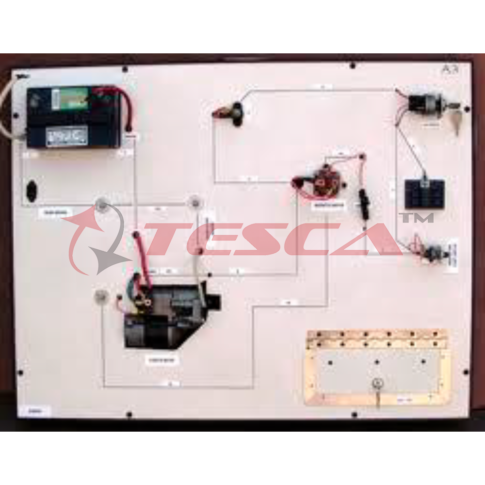
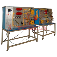
esca Car Electric Actuator Trainer 32541 have the main components of the car electric system fixed together on a board and can be operated on 12V means of a transformer-rectifier unit (220V/12V) System is mounted on M.S. Structure. Separate Teacher
SPECIFICATION
System Features
- Compact, comprehensive, sturdy design
- All working Systems can be studied to their operations.
- Basic Trainer instrumentation as optional attachments.
- Fault creation panel for teacher & faultfinding & remedies panel for students
- Slide, Charts, CBT as an optional Accessories
System Description
Tesca Car Electric Actuator Trainer 32541 have the main components of the car electric system fixed together on a board and can be operated on 12V means of a transformer-rectifier unit (220V/12V)
System is mounted on M.S. Structure. Separate Teacher panel will have facility of fault creation & student has to study all parameter & find the fault in the system.
There is different trouble shooting in the car electric circuit given as below which can solve by using a fault trainer.
Technical Specifications
- Colored schematic diagram with 5 LED for locating the tested components in the vehicle
- Analysis of fuel injector control signal with speed variation from 900~6000rpm and adjustable injection
- timing from 2ms~12ms
- Exhaust gas recirculation valve with test points for the analysis of the signal for adjusting the valve opening versus the duty cycle varying from 10%~90%
- Simulated common rail injector with test points for the analysis of the adjustments of:
- pre-injection time from 0.1~0.7ms
- delay of injection pulse from 0.7~4.5ms
- injection time form 0.2~1.8ms
- control frequency between 15Hz and 80Hz (900-4000rpm)
- injector opening pulse of 70V
- Stepper motor for idle control with 4 test points for the analysis of the signal on each winding
Regulation of pilot tone from 5Hz~50Hz; four LESs indicate the bias of windings Possibility of reversing the rotation direction and measurement on a milli-metric scale
Fault conditions:
Accessories like Horn and lightening not working properly.
The wire connections loose.
When we put the key in the ignition and go to start the car but the key doesn't turn.
Cut off and faulty actuator
Actuator in positive short circuit
Actuator in short circuit to earth
Interconnection and test points – Ø 2mm
Specifications:
- Starting system – Battery, starting motor, wiring, and switches
- Charging system – Alternator and regulator, with wiring
- Ignition system
- Teacher panel
- Student panel.
- Accessory system – Horns, lighting, instrument panel warning system.
Power Supply Unit:
Regulated voltage, electronically protected against short-circuits and overloads
Knob facility for selecting desired voltage
- Output 1: 1.3Vdc ÷ 24Vdc, 1A
- Output 2: 24/Vac – 0 – 24Vac, 0.5A
- Output 3: +5Vdc – 2A
- Output 4: +12Vdc – 2A
- Output 5: -12Vdc – 1A
- Input source: 220~230V AC, 50Hz, 1 Phase
Enquiry Form
Related Product
Tesca specialize in doing turnkey projects that is fully operable when it is handed over to the project authority. Starting from inception to application training, Tesca provides the services as ONE source solution. Working side by side with government authorities and people across the World, we help countries to perform better. We support countries grow their economies, strengthen their education and health systems and improve financial management. We do this by providing consultancy & training in environment safety, education, health strengthening.
Category
Useful Links
Contact Us
International Sales:
 91-9829132777
91-9413330765
India Sales:
91-9588842361
2026 © All Rights Reserved.