
Cyclonic Separation Trainer
Order Code: 32469
Category: Environmental Trainers
Tesca Cyclonic Separation Trainer 32469 is a method of removing particulates from an air stream through a vortex separation process. A high speed forced vortex rotating air flow is established within a cylinder called a cyclone. Cyclones are used wid...
SPECIFICATION
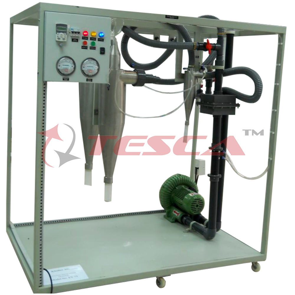
Tesca Cyclonic Separation Trainer 32469 is a method of removing particulates from an air stream through a vortex separation process. A high speed forced vortex rotating air flow is established within a cylinder called a cyclone. Cyclones are used widely in saw mills to remove saw dust from extracted air as well as oil refineries to separate oils and gases. This Cyclone Separation Trainer is used for demonstrating the basics of cyclonic vortex separation. The apparatus comprises of four main cyclones of different diameters, a dust feed system and an air supply blower. A venturi type flow meter is provided to measure the incoming air flow rates. Each cyclone is fitted with a particle collector for dust collection. Cyclones can be run individually or in series of any two. Air flow rates can be varied by controlling the air blower speed. A dust tank is provided to inject the dust into the system. Differential pressure measurement for individual cyclones are provided to measure the pressure drop across the cyclone and hence the velocity of air in the cyclone can be determined.
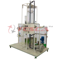
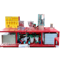
Tesca Cyclonic Separation Trainer 32469 trainer consists of three cyclone separators mounted on frame. Two cyclone separators are made of steel & one is made of glass. The cyclones can be arranged in such way that either one cyclone can be operated at a time or two cyclones can be operated in series. A high volume air blower which draws large volume of air through the cyclone separator. A hopper with control valve is used to feed dust particles in to the stream of air. The air mixed with particles then enters tangentially at the top inlet in the separator. The dust particles are separated in the separator & collected in container at the bottom. The filtered air leaves the separator through the outlet at the top. A Variable Speed Drive is used to vary the velocity & flow of air through the separator.
Each cyclone separator has glands to for measuring pressure difference across the cyclone. A differential pressure gauge is used to measure the differential pressure across cyclone. The air flow is measured by a venturimeter with differential pressure gauge.
Experiments Capabilities
- Understanding of air cyclone system.
- Demonstration of basic cyclonic separation
- Effect of input velocity against separation efficiency
- Effect of particle size on separation efficiency
- Cyclone diameter and conical construction on separation efficiency
- Single and double cyclone operation effects
- Comparison of pressure drop against input velocity
- To verify the theoretical relationship between pressure drop and inlet velocity
Technical Data
- Air Blower
- Capacity 280 m3/hr @ 3400 RPM,
- 5 hp 3 phase 415 V AC, 50 Hz
- Static Pressure: 20 kPa
- Blower Speed Control: Frequency Inverter
- Cyclone Material: Stainless Steel – 2 Nos, Borosilicate Glass -1 No.
- Cyclone Separator: Diameter 100 mm – 1 Nos.
- Cyclone Separator: Diameter 200 mm– 2 Nos.
- Dust Collector: Acrylic tank
- Dust Feeder
- Air Flow Meter: Venturimeter with differential pressure gauge
- No. of dust collector tank – 3 Nos.
- No. of differential pressure gauges – 2 Nos.
- Differential Pressure Range: 0-20 in of H2O
- Mobile Steel Structure
- Control Console: Coated Stainless Steel
Required Services
Electric Supply 415 V AC, Three Phase, 50 Hz.
Floor Space: 4 m x 2 m
Enquiry Form
Related Product


Tesca specialize in doing turnkey projects that is fully operable when it is handed over to the project authority. Starting from inception to application training, Tesca provides the services as ONE source solution. Working side by side with government authorities and people across the World, we help countries to perform better. We support countries grow their economies, strengthen their education and health systems and improve financial management. We do this by providing consultancy & training in environment safety, education, health strengthening.
Category
Useful Links
Contact Us
International Sales:
 91-9829132777
91-9413330765
India Sales:
91-9588842361
2026 © All Rights Reserved.