
Deformation of frames
Order Code: 32158
Category: Strength of Materials Lab
Features Elastic deformation of a statically determinate or indeterminate frame under point load U-shaped and S-shaped frame Principle of virtual work to calculate the deformation and support reaction in a statically indet...
SPECIFICATION
Features
- Elastic deformation of a statically determinate or indeterminate frame under point load
- U-shaped and S-shaped frame
- Principle of virtual work to calculate the deformation and support reaction in a statically indeterminate system
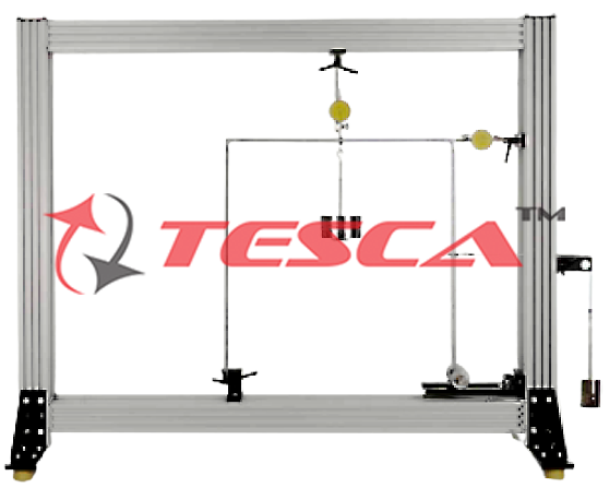
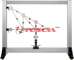
A frame is a bent beam with rigid corners which creates a so-called structure gauge. This means that it spans a gap while at the same time creating height.
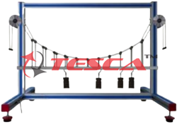
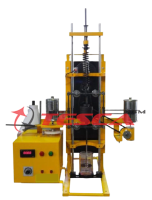
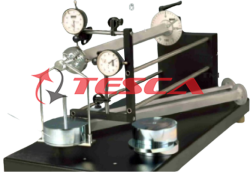
Tesca Deformation of Frames includes a typical U-shaped frame, such as is used in the construction of halls for example. One end is clamped into place, while the other can be loosely mounted. When the non-clamped end remains free, the statically determinate frame is investigated. A roller bearing on the non-clamped end creates a statically indeterminate frame. The frame is placed under load by two sets of weights. The load application points are movable. Two dial gauges record the deformations of the frame under load.
By applying various methods (first-order elasticity theory; the principle of superposition; and the principle of virtual work), the bending moment characteristics are ascertained for a statically determinate and indeterminate frame. From these characteristic curves and a chart for integrals (coupling table) the differential equation of the bend line is formulated. From the bend line and its derivations, displacements and the support force on the movable support can be calculated. A second, S-shaped frame can be used to show that the various methods are applicable to any kind of frame. All the component elements of the experiment are clearly laid-out and housed securely in a storage system.
The well-structured instructional material sets out the fundamentals and provides a step-by-step guide through the experiments.
Specifications
Investigation of the deformation of steel frames under load
U-shaped and S-shaped frame
Statically determinate or statically indeterminate bearing support possible
1 long and 1 short clamping pillar
Roller bearing for statically indeterminate support
Loading of the frame by weights
2 sets of weights with a movable hook to adjust to any load application point
Dial gauges record the deformation of the investigated frame under load
Storage system to house the components
Technical Specifications
Frame made of steel
- Edge length: 600mm
- Cross-section: 20x10mm
- U-shaped: 600x600mm
- S-shaped: 600x600mm
Dial gauges
- Measuring range: 0...20mm, graduations: 0,01mm
Weights
- 2x 1N (hanger)
- 8x 1N
- 6x 5N
Experiments
Relationship between load application and deformation on the frame
Differences between statically determinate and statically indeterminate frames
Familiarisation with the first-order elasticity theory for statically determinate and indeterminate systems
Application of the principle of superposition
Application of the principle of virtual work on statically determinate and statically indeterminate frames
- Determination of a deformation by the principle of virtual forces
- Determination of a load by the principle of virtual displacement
Comparison of calculated and measured deformations
Scope of Delivery
- 2 frames (1x U-shaped, 1x S-shaped)
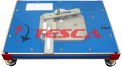
- 2 clamping pillars (1x long, 1x short)
- 1 support
- 2 sets of weights with movable hooks
- 1 deflection roller with fixture
- 1 cable
- 2 dial gauges with bracket
- 1 storage system with foam inlay
- 1 set of instructional material
Enquiry Form
Related Product
Tesca specialize in doing turnkey projects that is fully operable when it is handed over to the project authority. Starting from inception to application training, Tesca provides the services as ONE source solution. Working side by side with government authorities and people across the World, we help countries to perform better. We support countries grow their economies, strengthen their education and health systems and improve financial management. We do this by providing consultancy & training in environment safety, education, health strengthening.
Category
Useful Links
Contact Us
International Sales:
 91-9829132777
91-9413330765
India Sales:
91-9588842361
2026 © All Rights Reserved.