
Single Cylinder 4 Stroke Asynchronous Start Petrol Engine Test System With DAQ
Order Code: 32734
Category: Technology Trainers
System Features Compact and sturdy construction Easy and versatile operation Full performance tests possible Design for fail-safe operation Extensive choice of engines Rapid change over of engines Self contained- minimum service req...
SPECIFICATION
System Features
- Compact and sturdy construction
- Easy and versatile operation
- Full performance tests possible
- Design for fail-safe operation
- Extensive choice of engines
- Rapid change over of engines
- Self contained- minimum service required
- Highly flexible system permits easy Up gradation to computerized system
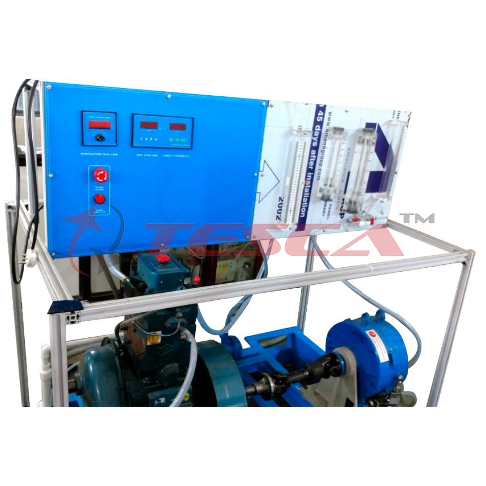
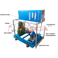
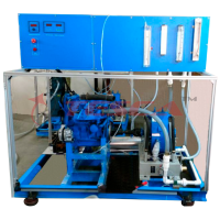
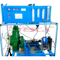
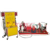
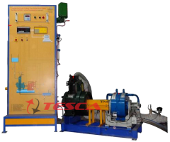
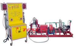
System Description
Tesca Automotive 4 Stroke Asynchronous Start Engine Test System 32733-32734 are designed for students to conduct experiments and study the performance of the engine. The engine uses asynchronous motor as brake system required to carry out experiments. The rig facilitates easy measurement of fuel consumption, air consumption, brake power and engine speed with data acquisition system (not applicable for Engines with speed regulation). Testing is carried out at different engine loads.
List of Experiments
- Measurement & Calculation of Volumetric efficiency.
- Measurement & calculation of specific fuel consumption
- Measurement & calculation of brake thermal efficiency
- Calculation Of Heat Balance sheet (optional if calorimeter ordered)
- Brake Mean Effective Pressure and brake power on the basis of engine speed (for Variable Speed Engine only).
- Plotting of exhaust temperature versus Speed
- Determining air / fuel ratios
- Engine torque, brake power and brake thermal efficiency
- Specific fuel consumption
- Exhaust temperature
- Gas emissions and analysis (optional)
General Specification
- Control and load unit for prepared four-stroke engines with a maximum power output of 11kW approx.
- Vibration-insulated base plate for mounting of the engine and the asynchronous motor
- Asynchronous motor with energy recovery unit as brake generates engine load
- Engine started by asynchronous motor
- Force transmission from engine to brake via elastic claw coupling
- Two separate fuel gauge systems
- Stabilisation tank for intake air 75L approx.
- Potentiometer for continuous adjustment of braking speed
- Measurement and display of temperatures (oil, fuel, air), engine load, engine speed, fuel consumption, air intake quantity, oil pressure
- Measured value displays for engine: exhaust gas temperature and cooling water temperatures
- Software for data acquisition (optional)
Technical Specifications
a) Asynchronous motor as brake
i) nominal power output: 11kW at 3000min-1
b) Energy recovery unit: 13kW
c) Measuring ranges
i) torque (approx. range): -200 to 200Nm
ii) speed (approx. range): 0 to 5000min-1
iii) intake air via differential pressure (approx. range): 0 to 938L/min
iv) temperatures (approx. range): 4x 0 to 120°C, oil: 1x 0 to 150°C, exhaust gas: 1x 0 to 900°C
v) cooling water flow rate (approx. range): 0 to 250L/h
vi) oil pressure (approx. range): 0 to 6bar
AutoSci-Cal® Engine Cycle Analyzer Module AMECA (Optional)
Features
- Significantly enhances practical investigations, demonstrations and studies of internal combustion engines
- For use with Smaller capacity Engine Test Sets and Regenerative Engine Test Set and engines
- Factory fitted with suitable cylinder head transducers and crank angle encoders
- Includes powerful Windows based software specially designed for educational use
- Automatic calculation and real-time display of p-q plots and p-V plots and other important parameters
- Useful snap-shot, replay and animation functions
- Accurate, clear animations of crank, piston, inlet and exhaust valve positions help students visualise the engine cycle
- Ideal for student experiments, laboratory demonstrations or project work, Engine Cycle Analyzer enables students to investigate a variety of engine performance characteristics.
- Students can export data for further analysis
Tesca Auto Sci-Cal Engine Cycle Analyzer Module AMECA is a module with hardware and software to measure internal combustion engine cylinder pressure and crank angle.
Tesca AutoSci-Cal Engine Cycle Analyzer Module AMECA is a versatile module consisting of both hardware and software specially designed for educational use. It enables students to investigate the relationship between crank angle or volume and the cylinder pressure in an internal combustion engine. The equipment is primarily for use with engine test sets and engines but it can also be used with other engines fitted with compatible cylinder head transducers and crank angle encoders.
The equipment consists of a hardware unit with connectors and leads, plus Windows based data acquisition and analysis software. The hardware consists of a microprocessor-based signal conditioning unit with high-speed PC interface, housed in a rugged, protective enclosure. It accepts and conditions signals from the Cylinder Head Pressure Transducer and Crank Angle Encoder, pre-mounted on the engines. The cylinder pressure input includes a precision charge amplifier with a digital calibration. Crank angle position, the signal from the Crank Angle Encoder is also used to determine engine speed.
The output from the hardware unit connects to a computer (computer not included) running the Engine Cycle Analyser software. The hardware unit includes LED indicators to show the processor readiness, encoder top deadcentre position and PC communication status.
The software provides real-time display of pressure versus crank angle (p-q) and pressure versus volume (p-V) plots.
It performs calculations on the data to accurately display indicated mean effective pressure (IMEP) and indicated power for comparison with brake mean effective pressure (BMEP), and brake power to determine the mechanical efficiency of the test engine.
The software has useful snap-shot, replay and animation functions to help students visualise and better understand the engine cycle. The snap-shot and replay allow students to capture several engine cycles and study them using an animation showing the relative position of the crank, piston, inlet and exhaust valves. The software also allows students to create and recall engine configuration files for convenient entry of test engine data needed for calculations such as crank radius and engine swept volume. Data can also be exported to other software for further analysis.
Experiment Possibilities
- Module AMESA allows investigations into a variety of internal combustion engine characteristics, including:
- The thermodynamic cycle of an internal combustion engine
- Calculation of indicated mean effective pressure and indicated power
- Comparison of indicated mean effective pressure and brake mean effective pressure
- Mechanical efficiency of the test engine
- Further work using exported data such as combustion analysis Extra Ancillaries (fitted on engines)
- Cylinder Head Pressure Transducer
- Crank Angle Encoder
Recommended computer hardware:
- Intel® Pentium® 4 or equivalent processor operating at 2 GHz
- 512 MB of RAM
- SVGA monitor with 16-bit colour, 1024 x 768 resolution
- CD-Rom drive
- USB 1.1 or 2 port
- 500 MB of hard disc space
- Two-button mouse
Operating system:
Microsoft® Windows XP, Vista, Windows 7 and 8
Standard Features
Supplied with comprehensive user guide
Made in accordance with the latest European Union Directives
Requirements:
Electrical supply:
Single-phase a.c. 90 to 240 V, 50/60 Hz
Operating Conditions
- Operating environment: Well ventilated laboratory
- Storage temperature range: –25°C to +55°C (when packed for transport)
- Operating temperature range: +5°C to +40°C
- Operating relative humidity range: 80% at temperatures < 31°C decreasing linearly to 50% at 40°C
Requirements at Site
- Power: 400V, 50/60Hz, 3 phase
- Water connection approx: 500L/h
- Ventilation and exhaust gas routing
Enquiry Form
Related Product


Tesca specialize in doing turnkey projects that is fully operable when it is handed over to the project authority. Starting from inception to application training, Tesca provides the services as ONE source solution. Working side by side with government authorities and people across the World, we help countries to perform better. We support countries grow their economies, strengthen their education and health systems and improve financial management. We do this by providing consultancy & training in environment safety, education, health strengthening.
Category
Useful Links
Contact Us
International Sales:
export@tesca.in
 91-9829132777
91-9413330765
India Sales:
indiasales@tesca.in
91-9588842361
2026 © All Rights Reserved.