
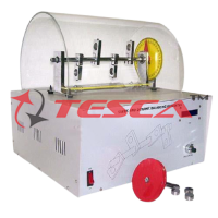
Torsion & Deflection Test Apparatus
Order Code: 32186
Category: Strength of Materials Lab
Features Tesca Torsion and Deflection Testing Apparatus allows a variety of experiments to be undertaken to investigate test specimens under torsional loading and bending loading within their elastic limits. The students cover topics involving bend...
SPECIFICATION
Features
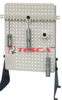
Tesca Torsion and Deflection Testing Apparatus allows a variety of experiments to be undertaken to investigate test specimens under torsional loading and bending loading within their elastic limits.
The students cover topics involving bending moment equation, torsional rigidity, modulus of rigidity, angle of twist, and create graphs and compare actual measured values with theoretical values using formulae and theory provided.
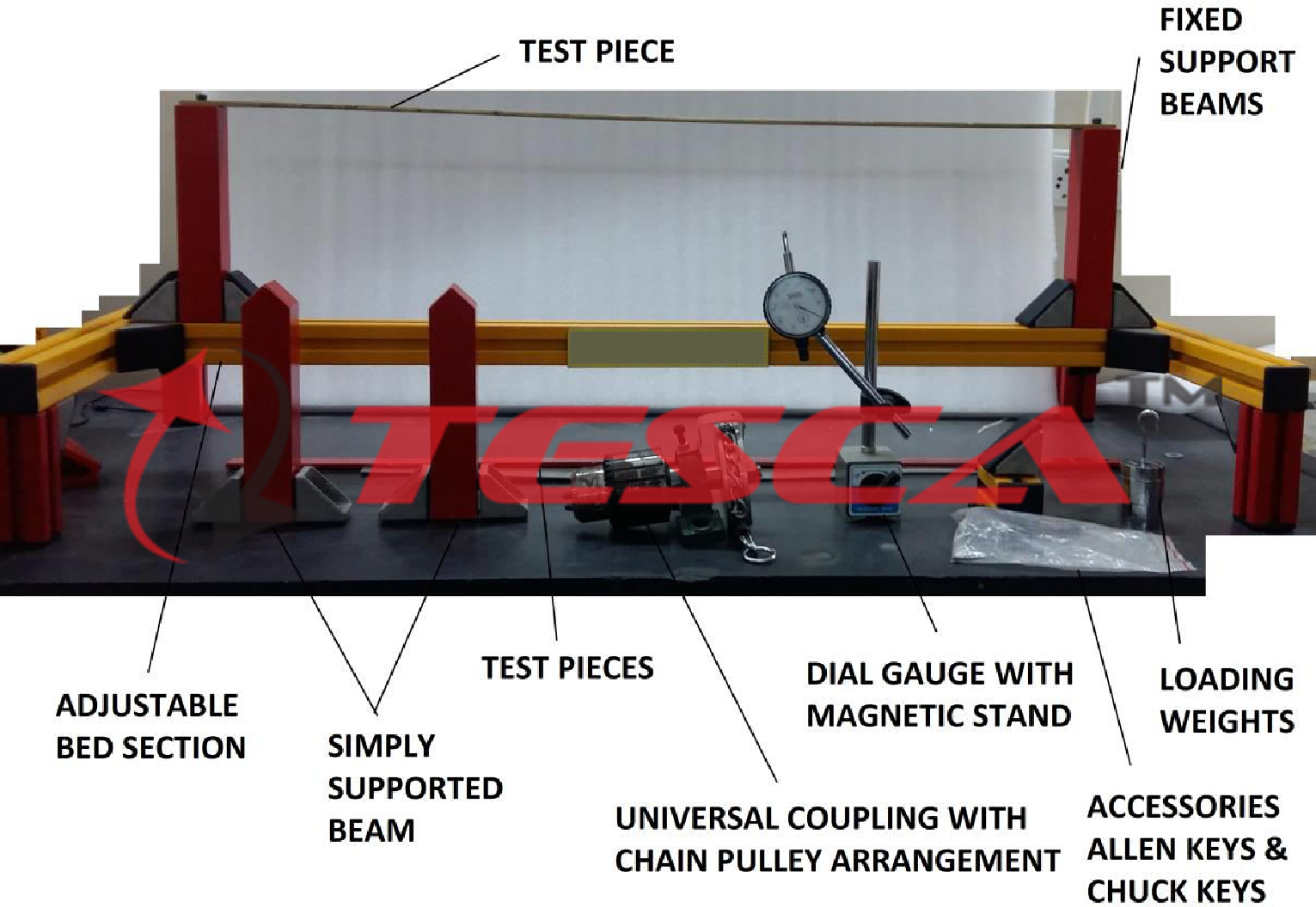
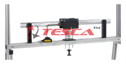
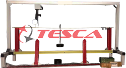
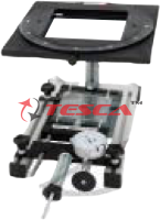
An extruded base frame carries two solid vertical supports. Profiled grooves within the base frame, fasteners and quick release handles ensure quick and easy adjustment of the span between the vertical supports.
One vertical support carries a unique specimen chuck with a through hole. Another chuck is held stationary at one end of the base frame. The chucks have two functions; to secure the torsion specimens during testing and to transmit the torsional loading to the torsion specimen. The torsional load is transmitted using a pulley and cord arrangement, with the pulley being mounted to a shaft running in bearings. The bearings minimize the friction in the system. The chuck installed into the vertical support has a through hole to allow the length of the torsion specimen to be varied.
The twist of the torsion specimens is indicated on an angle indicator and pointer, which can be moved along the test specimen.
The remaining vertical support is used for bending tests. Each vertical support has a top clamp provided. This allows the end support arrangement for the bending specimens to be varied, i.e. clamped, simply supported on knife edges or on ground dowels. The supports can be moved along the base frame thus changing the beam span.
To measure the bending specimen deflection a dial gauge is fixed onto a movable stand and can be positioned anywhere within the beam span.
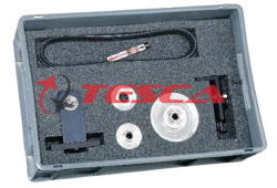
A set of torsion and bending specimens are supplied. A load hanger and set of calibrated weights create specimen loading.
A comprehensive instruction manual is included covering the apparatus, experimental procedure and example results. All necessary tools and accessories are supplied.
Specifications
Apparatus to test elastic deformation under bending and torsion
Compact, bench top, self contained unit
Specimens to be tested under bending and torsion
To have ability to change the end clamping arrangement for bending specimens
Chucks to secure torsion specimens and to apply torsion via pulley and hanger
Bending specimens to be supplied in a variety of cross section and materials
Torsion test specimens to be supplied in a variety of material
Apparatus to have adjustable beam span and torsion span
Deflections to be measured using dial gauge on movable stand
Torsion to be measured using movable protractor and pointer
Comprehensive technical manual for student and lecturer provided
To be provided with a set of calibrated weights, load hangers and all necessary accessories
Technical Specifications
Bending Specimens
Material: aluminum, steel and brass
- 25.4mm x 3.175mm x 450mm
- 4.76mm x 6.35mm x 450mm
- 19.05mm x 3.175mm x 450mm
Torsion specimens
Material: aluminum, steel and brass
Length with d=5mm: 450mm
Dial gauge: 0...10mm, graduations: 0,01mm
Tape measure, graduations: 0,01m
Load
1x 1N (hanger)
- 1x 1N, 1x 4N, 1X 5N, 1x 9N
Components List
One frame
Two bearing blocks
One device to generate the torque
Bending specimens
Torsion specimens
One dial gauge with bracket and one tape measure
One set of loads including hanger
Two hexagon socket wrenches
Two adjustable blocks with clamping chuck for torsion tests and supports for bending tests.
Loads to generate the bending or torque
Dial gauge with bracket
Storage system to house the components
Experiment Possibilities
Deflection of specimen as a function of loading force, material, Young’s Modulus of Elasticity (E), cross section, support span
Comparison of bending stiffness of varying specimen sections for the same cross sectional area
Comparison of cantilever beams, simply supported beams
Determination of Young’s Modulus of Elasticity (E) in shear for the different material specimens
Introducing Poissions Ratio
Torsion angle and clamping length relationship
Torsion angle and torsion moment relationship
Torsion angle and specimen cross section
Modulus of rigidity introduction
Enquiry Form
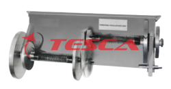
Related Product
Tesca specialize in doing turnkey projects that is fully operable when it is handed over to the project authority. Starting from inception to application training, Tesca provides the services as ONE source solution. Working side by side with government authorities and people across the World, we help countries to perform better. We support countries grow their economies, strengthen their education and health systems and improve financial management. We do this by providing consultancy & training in environment safety, education, health strengthening.
Category
Useful Links
Contact Us
International Sales:
 91-9829132777
91-9413330765
India Sales:
91-9588842361
2026 © All Rights Reserved.