
Turbine Set: Pelton, Francis, Kaplan
Order Code: 32098
Category: Fluid Mechanics Lab
Features : Comparison of impulse and reaction turbines1 Constant speeds and torques can be adjusted in combination Characteristics of a Kaplan turbine1 Adjustable guide vanes for setting the power output1 Water turbines...
SPECIFICATION
Features :
Comparison of impulse and reaction turbines1
Constant speeds and torques can be adjusted in combination
Characteristics of a Kaplan turbine1
Adjustable guide vanes for setting the power output1
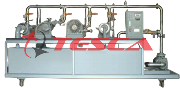
Water turbines are turbo-machines utilizing water power. They convert pressure and flow energy into mechanical energy and mostly are used for driving electrical generators. Water turbines can be divided into impulse and reaction turbines depending on their operating principle. Tesca Multi-Turbine: Pelton, Francis & Kaplan Turbines and Accessories contain a Pelton turbine as an example for an impulse turbine and a Francis turbine as an example for a reaction turbine. The two turbine types are examined and compared with each other together with the Turbine Supply Unit and the Universal Drive and Brake Unit. The drive unit offers the possibility to set constant speeds resp. torques. Thus you can realize experiments in different realistic operating modes.
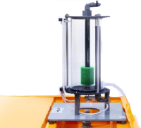
The Pelton turbine is a free-jet turbine that converts the pressure energy of the water into kinetic energy entirely in the control device. As the complete pressure difference is reduced exclusively in the nozzle, the pressure is constant in the impeller. The turbine is also known as a constant pressure turbine. The turbine power is controlled by adjusting the nozzle cross-section.
The Francis turbine converts the pressure energy of the water into kinetic energy in the control device and in the impeller. The pressure at the wheel inlet is higher than at the wheel outlet. The turbine power is controlled by adjusting the vanes in the control device.
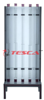
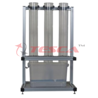
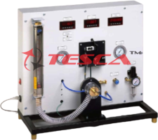
The Turbine Supply unit provides the water supply, the pressure measurement at the turbine inlet, and the flow rate measurement. In order to measure the pressure at the turbine outlet, the Francis turbine is equipped with an additional pressure sensor. Tesca Universal Brake and Drive Unit measures the braking torque and the speed.
The well-structured instructional material sets out the fundamentals and provides a step-by- step guide through the experiments.
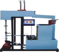
The Kaplan turbine is a reaction turbine with an axial through the flow. It has a high specific speed and is suitable for large water flows and small to medium heads. Therefore, the Kaplan turbine is used as a "classic" water turbine in run-of-the-river power stations.
Kaplan turbine helps to investigate the characteristic behavior of a simple-regulated Kaplan turbine during operation. The trainer is provided with a closed water circuit with a tank, submersible pump, and throttle valve for adjusting the flow rate. The angle of attack and thus the power output of the impeller is changed by adjusting the guide vanes. The turbine is loaded with a wear-free eddy current brake. The speed is captured by means of an inductive, non- contact position sensor at the turbine shaft. For determining the turbine power, the eddy current brake is equipped with a force sensor for torque measurement. The pressures at the inlet and outlet of the turbine, the temperature, and the flow rate are recorded with sensors. The recorded measured values are displayed digitally and processed further on a PC. The PC is used to calculate the power output data of the examined turbine and to 0represent them in characteristic curves.
Specifications:
Comparison of a Pelton turbine as impulse turbine and a Francis turbine as reaction turbine accessories for the Turbine Supply Unit
Operation by use of the Universal Brake and Drive Unit
Constant torques and speeds can be adjusted with Universal Drive and Brake unit
Transparent front panel in the turbines for observing the operating area
Adjustable nozzle needle for setting different nozzle cross-sections (Pelton turbine)
Adjustable guide vanes for setting different angles of incidence (Francis turbine)
A pressure sensor at the Francis turbine for measuring the pressure at the turbine outlet
Digital display for flow rate, pressures, and temperature in Turbine Supply Unit
Braking torque and speed measured in function of a Kaplan turbine
Closed water circuit with a submersible pump, throttle valve, and tank adjustment of flow rate with a throttle valve
Loading the turbine by use of air-cooled eddy current brake impeller with fixed vanes
Adjustable guide vanes for setting different angles of attack
Non-contact speed measurement at the turbine shaft and force sensor at the brake for measuring the torque
Digital display for pressures, temperature, flow rate, speed, and torque
Technical Specifications:
Translation ratio between brake and turbine: 1,44:1 Pelton turbine
Output: 1,5kW at 2750min-1 at 6,5bar
Wheel diameter: 165mm
Variable nozzle setting Francis turbine
Output: 1kW at 3500min-1 and 4,2bar
Wheel diameter: 80mm
Variable guide vane setting Kaplan turbine
Max. output: 1000W
Max. speed: 3700min-1
Control wheel
8 guide vanes, adjustable: -15°...45°
external diameter: 120mm, internal diameter: 60mm
Impeller, 4 vanes, fixed
external diameter: 120mm, internal diameter: 60mm, pitch: 80mm
Submersible pump with motor
Max. flow rate: 250m³/h
Max. pump head: 11m
Nominal power: 3,1kW Tank: approx. 350L Measuring ranges
Temperature: 0...100°C
Pressure (at turbine inlet): 0...1bar rel.
Pressure (at turbine outlet): -1...0,6bar rel.
- Flow rate: 13...200m³/h
Torque: 0...10Nm
- Speed: 0...6500min-1 Stroboscope
Covers the range of 250 - 18000 flashes per minute with an accuracy of ±2%.
Light source is an easily replaceable Xenon Flash Tube.
Optional:
Data Acquisition System
A PC with a Pentium processor
An electronic signal conditioning system
A stand-alone data acquisition modules
A Windows-based software Computer-Aided Learning
Multimedia features
Interactive
Graphic simulation
Experiment results samples
Full experiment manuals
Supervisory Control & Data Acquisition - Data Logging
Signal Analysis
Process Control
Real-Time Display
Tabulated Results
Graph of Experimental Results
Experiment Possibilities
Determination of mechanical output
Determination of efficiency
Recording of characteristic curves
Investigation of the influence of the nozzle cross-section on the power output
Determination of power output curves at different speeds
s Hydraulic power output
s Mechanical power output
Determination of the head
Determination of turbine efficiency
Investigation of the influence of the vane position on power output and efficiency
Services Required:
Mains power supply: 220-240V, 1Ph, 50Hz
Enquiry Form
Related Product

Tesca specialize in doing turnkey projects that is fully operable when it is handed over to the project authority. Starting from inception to application training, Tesca provides the services as ONE source solution. Working side by side with government authorities and people across the World, we help countries to perform better. We support countries grow their economies, strengthen their education and health systems and improve financial management. We do this by providing consultancy & training in environment safety, education, health strengthening.
Category
Useful Links
Contact Us
International Sales:
 91-9829132777
91-9413330765
India Sales:
91-9588842361
2026 © All Rights Reserved.