
Vertical Flow From Tank Apparatus
Order Code: 32078
Category: Fluid Mechanics Lab
Features: Determination of the diameter and velocity of the outlet jet1 Study of openings with different inlet and outlet contours1 Determining the contraction coefficient Pressure losses in the flow from tanks are essentially the result of two p...
SPECIFICATION
Features:
Determination of the diameter and velocity of the outlet jet1
Study of openings with different inlet and outlet contours1
Determining the contraction coefficient
Pressure losses in the flow from tanks are essentially the result of two processes: the jet deflection upon entry into the opening and the wall friction in the opening. As a result of the pressure losses, the real discharge is smaller than the theoretical flow rate.
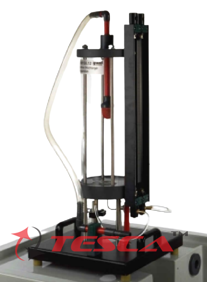
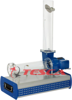
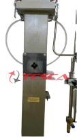
Tesca Vertical Flow from A Tank Apparatus determines these losses at different flow rates. Different diameters, as well as inlet and outlet contours of the openings, can be studied. Additionally, the contraction coefficient can be determined as a characteristic for different contours. The experimental unit includes a transparent tank, a measuring device as well as a pitot tube, and twin-tube manometers. An interchangeable insert is installed in the tank's water outlet to facilitate the investigation of various openings. Five inserts with different diameters, inlet contours, and outlet contours are provided along with the unit.
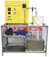
The issued water jet is measured using a measuring device. A pitot tube detects the total pressure of the flow. The pressure difference (read on the manometer) is used to determine the velocity. The tank is fitted with an adjustable overflow and a measuring point for static pressure. In this way, the level can be precisely adjusted and read on the manometer. The experimental unit is positioned easily and securely on the work surface of the HM 150 base module. The water is supplied and the flow rate measured by HM
150. Alternatively, the experimental unit can be operated by the laboratory supply.
The well-structured instructional material sets out the fundamentals and provides a step-by-step guide through the experiments.
Specifications:
Study of pressure losses in vertical flows from tanks
Determining the contraction coefficient for different contours and diameters
Tank with adjustable overflow
5 interchangeable inserts with different contours
Measuring device for determining the jet diameter
Pitot tube for determining the total pressure
Pressure display on twin-tube manometers
Flow rate determined by HM 150 base module
Water supply using HM 150 base module or via laboratory supply
Technical Specifications:
Tank
capacity: approx. 13L
overflow height: max. 400mm
max. flow rate: 14L/min Inserts
Inside diameters: d1=inlet, d2=outlet
1x cylindrical hole, d=12mm
1x outlet from the insert: cone d1=24mm, d2=12mm
1x inlet to the insert: orifice plate d1=24mm, d2=12mm
1x inlet to the insert: cone d1=30mm, d2=12mm
1x inlet to the insert: rounded, d=12mm Measuring ranges
pressure: 500mmWC
jet radius: 0...10mm
Experiments:
1. Study of the outlet jet (diameter, velocity)
2. Determination of pressure losses and contraction coefficient for different outlet contours
3. Determination of flow rate at different discharge heads
Services Required:
1. Mains power supply: 220-240V, 1Ph, 50Hz
2. Closed water circuit or ‘Tesca’ Hydraulic Bench 32096.
Enquiry Form
Related Product
Tesca specialize in doing turnkey projects that is fully operable when it is handed over to the project authority. Starting from inception to application training, Tesca provides the services as ONE source solution. Working side by side with government authorities and people across the World, we help countries to perform better. We support countries grow their economies, strengthen their education and health systems and improve financial management. We do this by providing consultancy & training in environment safety, education, health strengthening.
Category
Useful Links
Contact Us
International Sales:
 91-9829132777
91-9413330765
India Sales:
91-9588842361
2026 © All Rights Reserved.