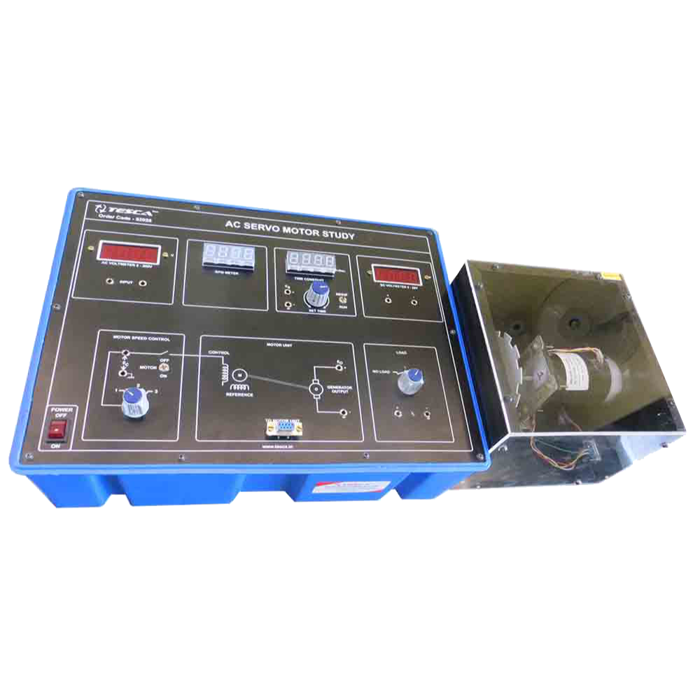
AC Servo Motor Trainer

Order Code: 23246952.4

Category: General Lab Equipment II

Features: Equipped with Rockwell Automation CSDJ Plus Servo Drive being widely used in industry PC-based control and monitoring through the computer software package ...


SPECIFICATION

Features:

  • Equipped with Rockwell Automation CSDJ Plus Servo Drive being widely used in industry
  • PC-based control and monitoring through the computer software package

Experiment:

  • Basic setting and operation of AC Servo Drive
  • How to set parameters of the servo motor
  • How to control the sequence of I/O signals and brake control signals
  • Operation of the servo motor by the Line Drive Output
  • Servo motor operation practices by the operators
  • Multiple speed control practices
  • Zero-clamp practices
  • Torque control practices

Specification:

  • Power source : Single-phase AC 220V (-15% ~ + 10%) , 50/60Hz
  • Control method: PWM control in use of IPM
  • Encoder : 2000 / 2048 / 2500 / 10000 P/R (incremental or absolute)
  • Ambient temperature : 0º ~ +50ºC (90% R.H)
  • Vibration / shock resistance : Vibration: 0.5G / Shock: 2G (1G = 9.8m/s2)
  • Position (output) : Encoder output: A-phase, B-phase and Zphase (MC3487 Line Driver)
  • External input : Servo ON/OFF, proportional control, forward/reverse rotation prevention, and alarm reset
  • External output : Brake control (in rotation), servo alarm/code (3-bit), speed compliance (speed control mode),position compliance (position control mode), Zpulse (opencollector)
  • Protective function : Overcurrent, overload, overvoltage, over speed, overheated inverter, CPU error, malfunctioned encoder, and communication disorder
  • Dynamic brake : To be activated in case of alarm activation
  • D/A output (speed) : Setting value (RPM) at ±1V/SET -08 (Max. ±10V)
  • D/A output (torque) : Setting value (%) at ±1V/SET -09 (Max. ±10V)
  • External indicator LED : Power ON, Servo Run, Servo Alarm
  • Command values such as speed, torque, position and electrical angle
  • Error values
  • Feedback values
  • Offset values
  • Load inertia ratio
  • PC software : All functions of Operator

Accessories:

  • Power cord : 1ea
  • Connection cable : 1set
  • Serial cable (9-Pin, D-SUB) : 1ea
  • PC software CD: 1ea
  • User's manual : 1ea

Typical activities include:

  • Describe the Main Elements of a PID Controller
  • Investigate the data capture features of a digital storage oscilloscope.
  • Conduct simple step, ramp, and frequency response tests.
  • Demonstrate Proportional Speed control.
  • Outline the reasons for adding velocity feedback.
  • Demonstrate the change in following error when transient velocity feedback replaces velocity feedback.
  • Discuss the effects of noise when subjected to derivative action
  • Demonstrate various combinations of PID control.
  • Demonstrate the stabilizing effect of a proportional action on system controlled with integral action.
  • Operate the software controls to drive the DC Motor and observe its behavior.
  • Measure the parameters of a plant using step tests.
  • Account for the excellent steady state performance of a proportional servo position system.
  • Set up a servo system to respond to ramp inputs using proportional gain and transient velocity feedback.
  • Show how positive feedback can occur in a negative feedback system.
  • Explain Gain Margin and Phase Margin.
  • Describe the advantages and disadvantages of using computers in real-time control.
  • Outline the problems arising from low resolution and slow sampling.
  • Describe Gray code position measurement and other absolute and relative digital position measurement techniques.
  • The Virtual Control Laboratory software should allow the control and monitoring of a DC motor module and command potentiometer, and it must includes the following items:
  • Real time Windows based Virtual
  • Control Laboratory software
  • CLIO Control laboratory input/output interface module
  • Parallel interface lead for connection between the interface module and the PC

The software must allows the user to divide the screen into four independently configurable sections:

  • Control Reference signal
  • Controller
  • Plant
  • Display

Items supplied with this Teaching Set should include:

  • D.C. Motor Control Module
  • Virtual Control Laboratory
  • Command Potentiometer
  • 4mm Connection Leads
  • Power Supply
  • Curriculum Manual Set

Standard Accessories: The equipment / instrument which are required to carry out the required experiment should come under standard accessories. The following accessories should be supplied along with this equipment: o Storage case/box

Enquiry Form