
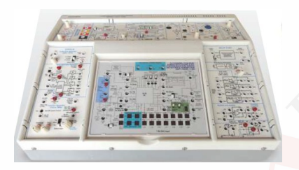
Advanced Digital Communication System
Order Code: 23246495.1.5
Category: General Lab Equipment III
KL-920 is implemented with high-speed MCU, DSP and highly flexible FPGA devices, giving students more opportunities to set up and observe digital data signals at each transmission stage. Learning topics include ASK...
SPECIFICATION
|
KL-920 is implemented with high-speed MCU, DSP and highly flexible FPGA devices, giving students more opportunities to set up and observe digital data signals at each transmission stage.
Learning topics include ASK / FSK transmission in wireless ISM band, FEC codec technique (block code and convolution code), digital data formatting (Preamble, ID, FEC and CRC), Manchester coding, SONET transportation frame (STS-1 and STM-1), TDMA, PCM, TDM, SD, CDMA, Digital filter, etc…
Features Specifications Complete digital transmitting data format including start bit, preamble, identifier, data with FEC coding, CRC coding, and stop bit All digital transmitting data are encoded with Manchester code before transmitting via ASK or FSK modulator. Programmable data, data rate, preamble, identifier, and noise from DIP switches FEC encoding, CRC mechanism, and Manchester coding can be included or ignored before wireless ISM transmission. Transmit and receive 3 sets of audio signals in TDMA channel via STS-1 and STM-1 frame Dual channel TDM transmission with an audio signal modulated by PCM or A-Law/ -Law compander
Specifications KL-96001 Main Unit 1. Dual function generators (1) Output waveform: Sine, Triangle, Square and TTL level signal
(2) Output voltage a. 1 Hz~50KHz 0 ~ 20Vpp continuously adjustable b. 50KHz~200KHz 0 ~ 16Vpp is continuously adjustable c. 200KHz~500KHz 0 ~ 10Vpp continuously adjustable (3) Output frequency: electable a. 1 Hz ~ 10 Hz continuously adjustable b. 10 Hz ~ 100 Hz continuously adjustable c. 100 Hz ~ 1KHz continuously adjustable d. 1KHz ~ 10KHz continuously adjustable e. 10KHz ~ 100KHz continuously adjustable . 100KHz ~ 500KHz continuously adjustable (4)AM modulation input a. Input amplitude : 0 ~ 5Vpp b. Input frequency range: 1 Hz ~ 100KHz c. Percentage modulation: 80% d. Output: AM amplitude continuously adjustable (5) FM modulation input a. Input amplitude : 0 ~ 5Vpp b. Input Impedance: 10KΩ c. Maximum modulation ratio: 50:1
(6) FSK modulation input a. Input impedance: 10K b. Input 0.7V for Low level, the adjustable output frequency Input 3V for High level, fixed output frequency
2. V/F converter (1) Input voltage : 0 ~ 20V (2) Output frequency : 0 ~ 20KHz (3) Conversion ratio: 1V = 1KHz 3. Adjustable DC power supply (1) Output voltage : 0 ~ 20V continuously adjustable (2) Maximum output current:100mA with overload protection 4. Fixed DC power supply (1) Output voltage: +5 V, -5V (rated current 500mA) (2) Output voltage : +12V, -12V (rated current 300mA) 5. Universal frequency/period counter (1) Function: Logic Probe/Frequency/Period/Pulse Width (2) Input frequency range: 1 Hz ~ 99.999999MHz 10 Hz ~ 100.00000MHz (3) Input period range: 0.01 μs ~ 999999.99 μs 1 μs ~ 99999999 μs (4) Input level: TTL, Analog signal (Vin ≥ 2.2Vpp) (5) Sampling time: 1 sec & 0.1 sec (6) Display: 8-digit, 7-segment display 6. Power input: AC 90 ~ 230V, 50/60Hz
KL-96021 ISM ASK/FSK Transceiver & DigitalData Encoder
1. RF carrier (1) Transceiver carrier frequency: 434.92MHz (2) Transmitter carrier power: 10dBm (3) Receiver carrier sensitivity: about -100dBm at 2.4Kbps (4) Modulation: ASK/ FSK selectable (5) IF signal : ASK (250KHz), FSK (150KHz) (6) Bandwidth of modulation: 100Hz ~ 16KHz 2. Data rate (1) 100/ 62.5Hz (3) 1.6K/ 1KHz (2) 160/ 100Hz (4) 16K/ 10KHz 3. Data transmission format (1) Start bit (2) 64-bit encoded data: 8-bit data encoded by 8-bit spread spectrum setting (3) Stop bit 4. Data transmission (1) Direct modulation (2) Manchester encoding 5. Data setting and display : 8-bit data set by High and Low key switches and LED display 6. Code division encoding and setting: 8-bit DIP switch
KL-96022 ISM ASK/FSK Transceiver & Digital Data Decoder 1. RF carrier (1) Transceiver carrier frequency: 434.92MHz (2) Transmitter carrier power: 10dBm (3) Receiver carrier sensitivity: about -100dBm at 2.4Kbps (4) Modulation: ASK/ FSK selectable (5) IF signal : ASK (250KHz), FSK (150KHz) (6) Bandwidth of modulation: 100Hz ~ 16KHz 2. Data rate (1) 100/ 62.5Hz (3) 1.6K/ 1KHz (2) 160/ 100Hz (4) 16K/ 10KHz 3. Decoder sampling frequency: 16X transmitted signal frequency 4. Received data decoding format (1) Start bit check (2) 8-bit spread spectrum code check (3) Stop bit 5. Data received (1) Direct demodulation (2) Manchester decoding 6. Received code division data display : 16 LEDs used for 64 bits data display, 16 bits x 4, selected by2 DIP switches 7. Decoded data display: 8 LEDs 8. Code division decoding set: 8-bit DIP switch
KL-96023 ID Code FEC (Block Code) Manchester Data Encoder /CRC/ /
1. Data rate (1) 100/ 62.5Hz (2) 160/ 100Hz
(3) 1.6K/ 1KHz (4) 16K/ 10KHz
2. Data setting and display : 8-bit data set by High and Low key switches and LED display 3. 8-bit data Forward Error Correction (FEC) mode : Two 16-bit Hamming codes (1) 4-bit data + 3-bit error-correcting code, two sets (2) 7-bit data + 4-bit error-correcting code, one set 4. 16-bit Hamming code display: 16 LEDs 5. 8-bit ID code setting: 8-bit DIP switch 6. CRC code: CRC-16 7. Data format: 58-bit data (1) Start bit (4) 16-bit FEC Hamming code (2) 16-bit preamble code (5) CRC-16 code (3) 8-bit ID (6) Stop bit 8. Data transmission (1) Direct modulation (2) Manchester encoding 9. Error code setting: 6-bit DIP switch 10. Data transmission via ISM FSK/ASK transceiver for RF remote data transfer
KL-96024 ID Code/ FEC (Block Code) / Manchester Data Decoder CRC/
1. Data rate (1) 100/ 62.5Hz (2) 160/ 100Hz
(3) 1.6K/ 1KHz (4) 16K/ 10KHz 2. 8-bit data Forward Error Correction (FEC) mode : Two 16-bit Hamming codes (1) 4-bit data + 3-bit error-correcting code, two sets (2) 7-bit data + 4-bit error-correcting code, one set 3. FEC data display : 8 LEDs for displaying 8-bit or 7-bit correct data received 4. 8-bit ID code setting: 8-bit DIP switch 5. CRC code: CRC-16 6. Data format: 58-bit data (1) Start bit detecting (2) 16-bit preamble code: detecting signal strength and synchronization
(3) 8-bit ID code check (4) 8/7-bit data decoded from 16-bit Hamming code (5) CRC-16 code check (6) Stop bit 7. Data received (1) Direct demodulation (2) Manchester decoding 8. Received data display : 16 LEDs for displaying 64-bit receive data (including CRC code)
9. Decoder output display: 8 LEDs 10. Decoding check (1) Flags for ID and CRC checks (2) Hamming code error bits detecting: 6 LEDs 11. Data transmission via ISM FSK/ASK transceiver for RF remote data transfer
KL-96025 ID Code/ FEC(Convolution) Manchester Data Encoder CRC /
1. Data format (1) Start bit (2) 32-bit data or 32-bit data interleave : 16-bit data setting via FEC convolution encoding (3) 8-bit ID code (4) 64-bit data transmission : 40-bit data plus CRC-16 code plus 8-bit ID (1/2 data rate)
2. Error code setting and transmitted data monitor (1) Combining 2-bit error byte address with 8-bit error setting for selecting error bits (2) 16 LEDs used for monitoring the transmitted data 3. Transmitted data can select Manchester encoding. 4. Data transmission via ISM FSK/ASK transceiver for RF remote data transfer
KL-96026 ID Code/ FEC(Viterbi)/Manchester Data Decoder CRC/ 1. Data received (1) Start bit detecting (2) 8-bit ID code check (3) 64-bit data: CRC-16 code calculation and detection (4) 32-bit data interleave setting (5) Viterbi algorithm for decoding correct 16-bit data 2. Manchester decoding 3. Data decoding and receiving LED display 4. Data receiving via ISM FSK/ASK transceiver for RF remote data transfer
KL-96027 ISM FSK/ ID Code/FEC/CRC/Transceiver Manchester/ 1. RF carrier (1) Transceiver carrier frequency: 433.2MHz (2) Transmitter carrier power: 15dBm (3) Receiver carrier sensitivity: about -105dBm at 100Kbps (4) Modulation: FSK (5) IF signal: 200KHz at 100Kbps (6) Bandwidth of modulation: 1KHz ~ 100KHz 2. Data transmission format (1) Programmable preamble: 2 or 4 bytes (2) Programmable Identifier: 2 or 4 bytes (3) Programmable data: 1 to 64 bytes (4) FEC Hamming encoding : FEC 4-bit data + 3-bit error-correcting code (5) CRC-16 (6) Manchester encoding and decoding 3. Transmission interface: SPI interface 4. Communicating with PC via SCI interface 1. Experiment module: 2 pcs 2. A computer is optional to carry out more experiments.
KL-96028 SONET TDMA-STS1 Multiplexer/Demultiplexer 1. TDMA modulation and transmission (1) Speech ADC sampling rate: about 8KHz (2) Speech ADC output: 7 bits (3) Transmission channels: 5 2. Data input: 5 sets set by five 8-bit DIP switches, 00-7FH (MSB=0), 2 of the five sets can be from a DIP switch or ADC 3. Preamble code: AAAA55H 4. TDMA transmission bits: 64 bits 5. TDMA transmission rate: about 512.8KHz 6. TDMA output signals : STS1 data, Frame Sync Transmit and bit Sync clock 7. TDMA reception and demodulation (1) From transmitter output STS1 data (2) Bit clock regeneration (3) Preamble code detect 8. TDMA demultiplexer outputs : 3 channels (24 bits, 8 bits each) indicated by LEDs, 2 of the 3 channels can select LED indications or DAC output 9. TDMA transmission rate: about 512.8KHz (FSX) (SYNCLK)
KL-96029 SONET TDMA-STM1 Data Encoder 1. Speech ADC sampling frequency: about 8KHz 2. Speech ADC output: 7 bits 3. Transmission channel : 3 sets of STS1 multiplexing transmission 4. Input data sets set by seven 8-bit DIP switches, 00-7FH 5. Preamble code: AAAA55AA55H 6. TDMA transmission bits: 160 bits 7. TDMA transmission rate: about 2.105MHz 8. Two STS1 data outputs 9. STM1 data: multiplexed output of three STS1 data inputs (MSB=0)
KL-96030 SONET TDMA-STM1 Data Decoder 1. Received STM1 data (1) Bit clock regeneration (2) Preamble code detect: AAAA55AA55H (3) Demultiplexer STS1 data : 3 sets 2. Demultiplexer output display:7x8 LEDs 3. TDMA transmission rate: about 2.105MHz
KL-96031 TDM/CODEC; PCM/PWM; DSP-FIR Module 1. TDM-SADC-SDAC-CODEC (1) Codec module: TI TLV320AIC23 chip (2) Stereo TDM (Time Division Multiplexing) signal (3) TDM signal sources a. Internal signal generator: Left-sine wave, Right -triangle wave b. External line and microphone inputs
2. ADC-PCM-SDAC-PWM (1) ADC module a. Resolution: 12 bits b. Maximum sampling rate: 2MHz (2) PCM (Pulse Code Modulation) a. PCM transmission: SPI bus b. Switch-selected 4-channel inputs (3) PCM-SDAC: PCM data to analog signal via SDAC (4) PWM (Pulse Width Modulation) PWM resolution: 12 bits (5) ADC Parallel Output and Scanned Display a. Inputs: 4-channel inputs from ADC outputs b. Outputs:12-bit parallel TTL-level output, LED indications c. ADC output data display:4-digit 7-segment LED scanned display
KL-96032 DSSS/CDMA Encoder & Decoder 1. CDMA Encoder (1) CDMA encoder channels : 3 channels (2) Data input of each channel: 8-bit DIP switch setting (3) PN code input of each channel: 8-bit DIP switch setting (4) CDMA encoded sum sequence: 4 bits 2. DS Generator (1) Sine, nine and square wave generator Frequency range : 300Hz ~ 10KHz adjustable, ±20% (2) 3-channel DS encoder 3 CDMA spread-spectrum signals for BPSK modulation (3) Multi-channel DS carrier generator BPSK sum QAM output signal with adjustable gain (Gain value: 1~2) 3. CDMA Decoder (1) PN code: 8-bit DIP switch setting (2) CDMA multiplier output: 5 bits (4) CDMA accumulator output (5) CDMA accumulator sign detecting (6) CDMA decoded data-word output 4. DS Decoder (1) Multiplying BPSK sum by PN sequence in DS multiplier decoder (2) BPSK sync clock delay adjustment (3) BAPSK (Binary Amplitude Phase Shift Keying) outputs (4) CDMA BAPSK demodulator (5) 5-bit DS add-accumulate processing and sign detecting (6) DS decoded data-word output
KL-96033 PCM-TDM-Compander Modulation/Demodulation 1. PCM-TDM-Compander (A-/μ-Law) Modulation (1) 8-bit ADC Module a. Strobe signal: 8KHz b. 4Vpp positive and negative signal levels adjustment c. Input audio frequency: 100Hz ~ 2KHz d. PCM output: 8-bit parallel data PCM to serial TDM output (2) 14-bit μ-Law and 13-bit A-Law audio compression to TDM output a. Switch-selected 14-bit μ-Law or 13-bit A-Law compression b. Converting A-/μ-Law input data set by a 14-bit DIP switch to 8-bit compressed data c. A-/μ-Law compressed 8-bit output indication: 8 LEDs d. A-/μ-Law compression rate: at least 1MHz (3) TDM transmitter system a. Operating frequency: 20MHz b. Multiplexer bits: preamble (55AAH) plus 32-bit data c. Bit clock: 434KHz or higher d. Frame Sync Transmit (FSX) frequency: at least 46KHz e. Master/slave setting f. TDM output: TTL-level Q and open-collector NQ g. Connecting two sets of 16-bit data for TDM master/slave multiplexing transmission
2. PCM-TDM-Compander (A-/μ-Law) Demodulation (1) 8-bit DAC module a. Signal analogue output: R-2R buffer and level shifter b. Audio output frequency: 100Hz ~ 2KHz (2) 14-bit μ-Law and 13-bit A-Law expanding a. Switch-selected 14-bit μ-Lawor13-bitA-Law audio expanding b. 14/13-bit expanded output indicated by LEDs (3) TDM receiver system a. Operating frequency: 20MHz b. Demultiplexer bits: preamble (55AAH) plus 32-bit data c. Bit clock: 434KHz produced by clock regeneration d. Master/slave demultiplexing setting
Technical Clauses:
The bidder must present a manufacturer authorization
|
Enquiry Form
Related Product

Tesca specialize in doing turnkey projects that is fully operable when it is handed over to the project authority. Starting from inception to application training, Tesca provides the services as ONE source solution. Working side by side with government authorities and people across the World, we help countries to perform better. We support countries grow their economies, strengthen their education and health systems and improve financial management. We do this by providing consultancy & training in environment safety, education, health strengthening.
Category
Useful Links
Contact Us
International Sales:
 91-9829132777
91-9413330765
India Sales:
91-9588842361
2026 © All Rights Reserved.