
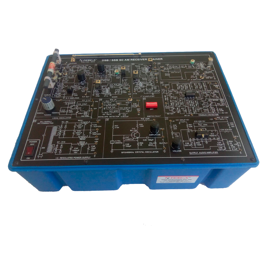
AM Receiver Trainer
Order Code: 23246934.84
Category: General Lab Equipment III
DSB / SSB AM Receiver trainer this trainer has been designed with a view to provide practical and experimental knowledge of DSB / SSB AM Receiver technique as practically implemented in Analog Communication system on a signal P.C.B. of size 300x400m...
SPECIFICATION
DSB / SSB AM Receiver trainer this trainer has been designed with a view to provide practical and experimental knowledge of DSB / SSB AM
Receiver technique as practically implemented in Analog Communication system on a signal P.C.B. of size 300x400mm
Object:
01. Study of DSB & SSB AM reception & deletion by diode / product detectors.
02. Study of AGC.
03. Study of receiver tuned circuits.
04. Study of Sensitivity, Selectivity & Fidelity of Receiver.
Experiments:
01. Study of double sideband AM reception using envelope detector via cable.
02. Study of double sideband AM reception using envelope detector via Antenna.
03. Study of sensitivity, selectivity, of a radio receiver.
04. Study of single sideband AM reception using product detector.
05. Study of Image frequencies.
06. Voice transmission with DSB AM transmission / reception.
Feature:
The board consists of the following built-in parts:
01. POWER SUPPLY : ± 12DC and +5V DC IC Regulated power supply.
02. Detectors/Demodulator : 1. Diode Detector (For DSB)
: 2. Product Detector (For SSB)
03. Frequency Range : 980KHz to 1650 KHz.
04. Intermediate frequency : 455 KHz.
05. Input Circuits : 1. RF Amplifier
: 2. Mixer
: 3. 1st Amplifier
: 4. 2nd Amplifier
: 5. Local oscillator
: 6. Envelope Detector (AGC)
: 7. Switch Fault
: 8. Product Detector
: 9. IC Regulated Power Supply
: 10. Beat frequency oscillator / 455 KHz Crystal oscillator
: 11. Output Audio Amplifier
06. Receiving media : Telescopic Antenna / cable.
07. Tuning : with variable capacitor.
08. Switched faults : 8Nos.
09. Test points : 50.
10. Power supply requirement : 230V AC, 50 Hz.
11. Mains ON/OFF switch, fuse and LED.
12. Audio Output amplifier with Volume Control.
13. Loud Speaker with baffle fitted in a box with two metre wire and 2mm Banana pins for connections.
- Adequate no. of patch cords stackable from rear both ends 2mm spring loaded plug length ½ metre.
- Good Quality, reliable terminal/sockets are provided at appropriate places on panel for connections/ observation of waveforms.
- Strongly supported by detailed Operating Instructions, giving details of Object, Theory, Design Procedures, Report Suggestions and Book References.
Other Apparatus Required:
- Cathode Ray Oscilloscope 20MHz
Enquiry Form
Related Product

Tesca specialize in doing turnkey projects that is fully operable when it is handed over to the project authority. Starting from inception to application training, Tesca provides the services as ONE source solution. Working side by side with government authorities and people across the World, we help countries to perform better. We support countries grow their economies, strengthen their education and health systems and improve financial management. We do this by providing consultancy & training in environment safety, education, health strengthening.
Category
Useful Links
Contact Us
International Sales:
 91-9829132777
91-9413330765
India Sales:
91-9588842361
2026 © All Rights Reserved.