
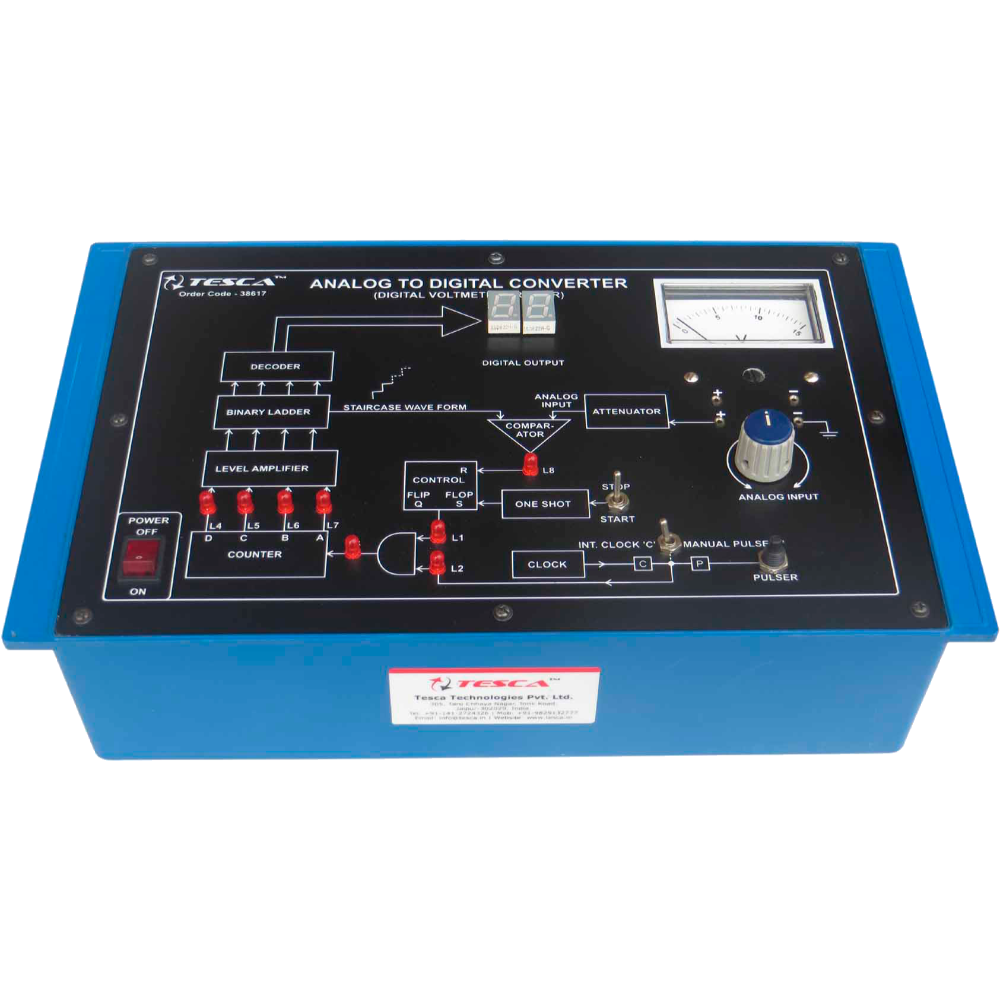
Analog to Digital Converter Trainer
Order Code: 23246825.7
Category: General Lab Equipment III
Computer Logic Training Board has been designed specifically for the study of Analog to Digital Converter. The board is absolutely sel contained and requires no other apparatus. Practical experience on this board carries great educative value for ...
SPECIFICATION
Computer Logic Training Board has been designed specifically for the study of Analog to Digital Converter. The board is absolutely sel contained and requires no other apparatus.
Practical experience on this board carries great educative value for Science and Engineering Students.
Object:
- To study the basic principle on conversion of analog signal to digital signal.
- To study the working of Digital Voltmeter.
Features:
The board consists of the following built-in parts :
- + 5V D.C. at 250mA, IC Regulated Power Supply internally connected.
- - 5V D.C. at 50mA, IC Regulated Power Supply internally connected.
- + 10V D.C. at 50mA, IC Regulated Power Supply internally connected.
- 0-15V D.C. at 50mA, continuously variable Power Supply.
- D.C. Voltmeter, 65mm rectangular dial to read 0-15V.
- Voltage comparator.
- Quad 2-input NAND gate.
- Quad 2-input NOR gate.
- Qual 2-input AND gate.
- Dual 4-input AND gate.
- Quad 2-input EX-OR gate.
- Three, Hex Buffer/Driver.
- BCD-to-7 Segment Decoder/Driver.
- Dual J-K Flip-Flop.
- 4-Bit Binary Ripple Counter.
- Timer.
- Continuous monitoring of analog signals on a voltmeter and of digital signals on 7 segment display.
- Seven LEDs to display the state of various important points.
- Two seven segment displays for visual indication of output status.
- Provision for manual pulses as well as for internal clock.
- Adequate no. of other Electronic Components.
- Mains ON/OFF switch, Fuse and Jewel light.
- Adequate no. of patch cords stackable from rear both ends 4mm spring loaded plug length ½ metre.
- Good Quality, reliable terminal/sockets are provided at appropriate places on panel for connections / observation of waveforms.
- Strongly supported by detailed Operating Instructions, giving details of Object, Theory, Design procedures, Report Suggestions and Book References.
Specifications:
- Analog signal variation : 0 to +15V
- Digital word length : 4 bits
- Decoder display : 0 to 15
- (using 7-segments)
- Leds indications : LED will glow for ‘1’ state and will be OFF for ‘0’ state.
- Supply required : 230V ±10% at 50Hz A.C. Mains.
Enquiry Form
Related Product


Tesca specialize in doing turnkey projects that is fully operable when it is handed over to the project authority. Starting from inception to application training, Tesca provides the services as ONE source solution. Working side by side with government authorities and people across the World, we help countries to perform better. We support countries grow their economies, strengthen their education and health systems and improve financial management. We do this by providing consultancy & training in environment safety, education, health strengthening.
Category
Useful Links
Contact Us
International Sales:
 91-9829132777
91-9413330765
India Sales:
91-9588842361
2026 © All Rights Reserved.