
Basic Electronics/Communication Trainer
Order Code: 23246911.11
Category: General Lab Equipment III
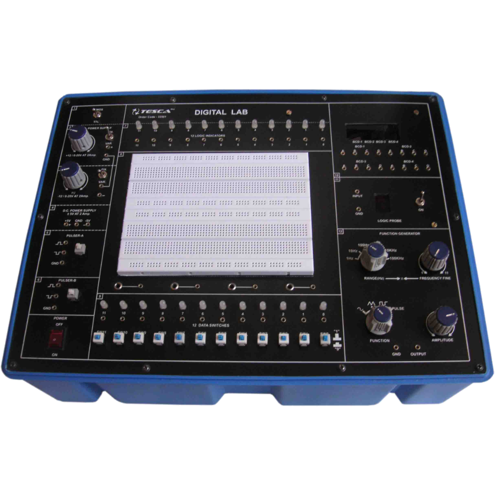
The DIGITAL LAB is intended for elementary as well as advance training of digital electronics. The digital lab covers regular digital circuits by solder-less interconnections on breadboard and as well as compatible with all optional modules through u...
SPECIFICATION
The DIGITAL LAB is intended for elementary as well as advance training of digital electronics. The digital lab covers regular digital circuits by solder-less interconnections on breadboard and as well as compatible with all optional modules through use of 2mm brass terminals and patch cords. Various clock generators, logic level input/output indicators and DC regulated power supplies etc. are in-built. The unit housed in attractive enclosure is supplied with mains cord, patch cords, Instruction manual and Component Set.
Experimental Coverage:
01. Logic gates operation
02. To verify De-morgan’s theorem with boolean logic equations
03. Binary to Gray code conversion
04. Gray code to Binary conversion
05. Binary to Excess-3 code conversion
06. Binary Adder and Subtractor
07. Binary Multiplier
08. EX-OR gate implementation
09. Application of EX-OR gate
10. Johnson Counter
11. To verify the dual nature of Logic Gates
12. Study of Flip-Flops RS, JK, D&T
13. Multiplexer and Demultiplexer
14. 4 Bit Binary up and down counter
15. Study of 8 to 3 Line Encoder
16. Study of 3 to 8 Line Decoder
17. Study of Shift Register (SIPO)
18. CMOS-TTL Interfacing
19. Study of Crystal oscillator
20. Study of pulse stretcher circuit
Features:
Bread Board : Unique solder-less large size, spring loaded breadboard consisting of two Terminal Strips with 1280 tie
points and 4 Distribution Strips with 100 tie points each, totaling to 1680 tie points. (Size : 112mm x
170mm approx)
Regulated DC Power Supply : +5V at 1 Amp, -5V at 500 mA, 3 to +15V at 500mA, and -3 to -15V at 500 mA.
Pulse Generator : 1 Hz to 1 MHz in 6 Steps. Variable in between steps
- Amplitude : 3-15V (CMOS), 5V (TTL)
- Duty Cycle : 50% TTL / CMOS Output
Pulsar Switches : 2 independent buffered bounce free manual pulser (useful for freezing the action of each stage of the
counter after every clock pulse)
Data Switches : 12 Nos. independent buffered logic level inputs to select High / Low TTL levels, each with a bi-color
LED to indicate high / low status and termination.
Logic Indicators : 12 Nos. independent buffered logic level indicators for High / Low status indication with bi-color LED
for digital outputs`
OPTIONAL MODULES:
Apart from above given experimental coverage of 20 experiments on breadboard, customers can purchase these optional modules. These are ready to use modules with wired components & circuit schematic drawn on top compatible to use with Digital Lab.
Enquiry Form
Related Product
Tesca specialize in doing turnkey projects that is fully operable when it is handed over to the project authority. Starting from inception to application training, Tesca provides the services as ONE source solution. Working side by side with government authorities and people across the World, we help countries to perform better. We support countries grow their economies, strengthen their education and health systems and improve financial management. We do this by providing consultancy & training in environment safety, education, health strengthening.
Category
Useful Links
Contact Us
International Sales:
 91-9829132777
91-9413330765
India Sales:
91-9588842361
2026 © All Rights Reserved.