
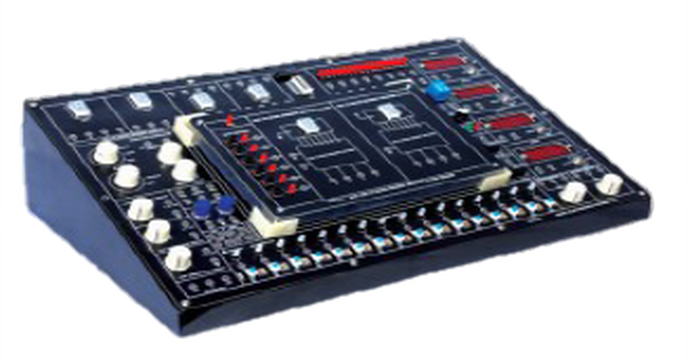
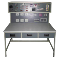
Basic Electronics Trainer
Order Code: 22236246.2
Category: General Lab Equipment II
Experiment Performed Module One Basic Electronic Circuits Diode and Transistor Switches Basic applications of Operation Amplifiers (I) Experiment 4: Inverter OP Amplifier fin 1 kHz and 2 VPP Experiment 5: Inverter fin 1 kHz and...
SPECIFICATION
Experiment Performed
Module One
- Basic Electronic Circuits
- Diode and Transistor Switches
- Basic applications of Operation Amplifiers (I)
- Experiment 4: Inverter OP Amplifier fin 1 kHz and 2 VPP
- Experiment 5: Inverter fin 1 kHz and 2 VPP
- Experiment 6: Non-Inverter OP Amplifier fin 1 kHz and 2 VPP
- Experiment 7: Voltage Follower fin 1 kHz and 2 VPP
- Basic Applications of Operation Amplifiers (II)
- Experiment 8: Comparator Vs ±12 V,V ref ±1 V
- Experiment 9: Zero Crossing Detector Vs ±12 V , V ref 0 V
- Experiment 10: Photoelectric Controller Vs ±12 V , V ref 6 V
Module Two
- Waveform Generator Circuits
- Schmitt Trigger Circuit
- Experiment 1: Schmitt Trigger Vs ±12 V , fin 1 kHz, Vin and 10 VPP
- Experiment 2: 555 Delay Circuit Vs 12 V , TON 6 secs
- Experiment 3: Delay Turn off Circuit VCC 12 V ,TON 4 ~ 9 secs
- Astable Multivibrator
- Experiment 4: OPA Astable Multivibrator Vs ±12 V , V out 22 VPP Square wave
- Experiment 5: 555 Astable Multivibrator VCC 12 V , V out 11 VPP Square wave
- Experiment 6: Sparkling Lamp
- Crystal Oscillator
- Experiment 7: TTL Crystal Oscillator for 100 kHz ~ 4 MHz
- Experiment 8: OPA Crystal Oscillator for 1 MHz, V out and 6 VPP
Module Three
- Digital Circuits
- BCD Adder
- Experiment 1: BCD Adder IC 4560B
- BCD Subtractor
- Experiment 2: BCD Subtractor IC 4560B
- Applications of Timer
- Experiment 3: Monostable Circuit VCC 12 V , TON 5 ~ 10 secs dot
- Experiment 4: Touch Switch VCC 12 V , TON 5 secs
- Experiment 5: Alarm Circuit VCC 5 V , IC LM555, Speaker
- Digital Display Circuit
- Experiment 6: 4518 Counter
- Experiment 7: Digit Display Circuit VCC 5 V, IC CD4518
- Application of LCD
- Experiment 8: LCDM Circuit VCC 5 V, IC: 4511
Module Four
- Signal Process Circuits
- Digital to Analog Converter
- Experiment 1: R 2R Ladder Network Circuit VCC 8 V, V out= 0 ~ 7.5 V
- Experiment 2: D byA Converter VCC ±15 V, IC DAC0800
- Analog to Digital Converter
- Experiment 3: A/D Converter VCC 5 V, IC ADC0804
- Filters
- Experiment 4: Low pass Filter VCC ±15 V, fin 100 Hz ~ 5 kHz and 4 VPP
- Experiment 5: High pass Filter VCC ±15 V, fin 100 Hz ~ 5 kHz and 4 VPP
- Experiment 6: Bandpass Filter VCC ± 15 V , fin 50 Hz ~ 280 Hz and 4 VPP
- Experiment 7: Bandstop Filter VCC ± 15 V, fin 50 Hz ~ 280 Hz and 4 VPP
Module Five
- Regulated DC Power Supply
- Applications of 7800 Series Regulator
- Experiment 1: 7805 Regulator Characteristic Vin 8 ~15 V, V out =5 V
- Experiment 2: 7805 Expanded Voltage Vin 12 V,V out =5 ~ 7 V
- Experiment 3: 7805 Variable Regulator Vin 12 V, V out =11 V
- Experiment 4: 7805 Current Source RL 0 ~330Ω, I out= 10 mA
- Applications of 7900 Series Regulator
- Experiment 5: 7905 Regulator Characteristic Vin 8 ~15 V, Vout =-5 V
- Experiment 6: 7905 Expanded Voltage Vin 12 V, V out = -5 ~ -7 V
- Experiment 7 7905 Variable Regulator Vin 12 V, V out = -11 V
- Experiment 8 7905 Current Source RL 0 ~330Ω, I out =11 mA
- Function Generator and DC Power Supply
- Waveforms: Sine, Triangle, Square and TTL Pulse
Technical Specification
Amplitude: 10Vpp
- Impedance: 50Ω ±10 %
- Duty Control: 30 % to 60%
- Display: 6 Digit LED
- Frequency Range: 10Hz to 100 kHz 4 Ranges
- Frequency Range: 100Hz to 1 MHz 4 Ranges
- Constant Voltage Output: ± 5V,±12V
- Variable Voltage Output: 0 V to ±15V
- Power source 220 to 230V AC 50Hz 1 Phase
Enquiry Form
Related Product


Tesca specialize in doing turnkey projects that is fully operable when it is handed over to the project authority. Starting from inception to application training, Tesca provides the services as ONE source solution. Working side by side with government authorities and people across the World, we help countries to perform better. We support countries grow their economies, strengthen their education and health systems and improve financial management. We do this by providing consultancy & training in environment safety, education, health strengthening.
Category
Useful Links
Contact Us
International Sales:
 91-9829132777
91-9413330765
India Sales:
91-9588842361
2026 © All Rights Reserved.