
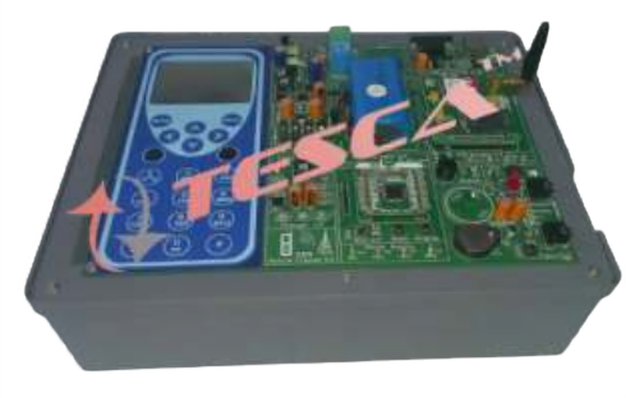
Cellular Mobile Training System
Order Code: 23246296.1
Category: General Lab Equipment II
Programs to be Performed: - GSM (Global System for Mobile Communication) standard- GSM Cellular Network and Radio cell - MS (Mobile Station)- BTS (Base Transceiver Station)- - BSC (Base Station Controller)- - MSC (Mobile Switching Center)- Channel ...
SPECIFICATION
Programs to be Performed:
- GSM (Global System for Mobile Communication) standard- GSM Cellular Network and Radio cell
- MS (Mobile Station)- BTS (Base Transceiver Station)- - BSC (Base Station Controller)- - MSC (Mobile Switching Center)- Channel Coding- Gaussian Low-Pass Filter- GMSK (Gaussian Minimum Shift Keying) modulation- GSM bands- TDMA (Time Division Multiple Access) technology- Functional characteristics of cellular telephone- Measurements on different circuits of cellular trainer- Wireless communication- 2 bi-directional connections between 4 users - Troubleshooting
Technical Parameters:- Display: 16 character x 2 lines- Keyboard: 4 lines x 4 columns- DTMF (Dual Tone Multi Frequency): Telephone tone generator and 2-Band filter decoder- DSP IC: - - it generates DTMF signal- - it uses the keyboard for data input- - it shows the number selected on the display- PIC IC manages: Display, Keyboard and Calls- Built-in loudspeaker with adjustable power amplifier- Selections: Dialing, Incoming call answer and Radio channel- Channel Coding:- - PCM (Pulse Code Modulation)- - 8-bit word: 13-bit linear to pseudo-log 8-bits ADC (and DAC) by data companding-
- 8-kHz sampling frequency- - baud rate of 64 kb/s
- TDMA Frame: 4 user time slots, 1 synchronism time slot, Time slot display
- Smoothing Filter- UHF Transmitter and Receiver:
- 4 selectable channels by PLL circuit-
- RF channel frequency: 2400 to 2481 Mhz
- In/Out Impedance: 50 Ω
- Transmitter Output RF Power: ≥ 10dBm
- Channel Noise simulator
- Channel Attenuation simulator
- 2 Stylus Antennas
- Compact and strong metal box including:
- Lift-able cover with block diagram
- Electronic components and power supply
- Schematic diagram including signaling LEDs, selection switches and Measuring test points
- Fault simulator: protected with key-locked cover and including 10 faults insert-able by switches
- Cables and Microphone- Power source: 220~230V AC, 50Hz, 1 Phase- Standard accessories with printed operation manual
Enquiry Form
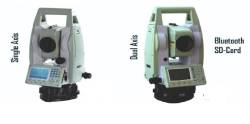
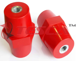
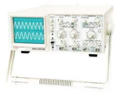
Related Product

Tesca specialize in doing turnkey projects that is fully operable when it is handed over to the project authority. Starting from inception to application training, Tesca provides the services as ONE source solution. Working side by side with government authorities and people across the World, we help countries to perform better. We support countries grow their economies, strengthen their education and health systems and improve financial management. We do this by providing consultancy & training in environment safety, education, health strengthening.
Category
Useful Links
Contact Us
International Sales:
 91-9829132777
91-9413330765
India Sales:
91-9588842361
2026 © All Rights Reserved.