
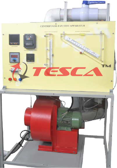
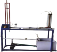
Centrifugal Blower Apparatus
Order Code: 32049
Category: Fluid Mechanics Lab
Features: Mobile, compact, comprehensive, sturdy design Complete instrumentation for the study of Centrifugal blower performance at different pressures, speeds & flow rates. Data Acquisition System as an optional accessory. 2. Plottin...
SPECIFICATION
Features:
Mobile, compact, comprehensive, sturdy design
Complete instrumentation for the study of Centrifugal blower performance at different pressures, speeds & flow rates.
Data Acquisition System as an optional accessory.
2. Plotting of intake volume flow rate versus delivery flow rate for varying duty.
3. Calculation of centrifugal fan/blower performance under variable speed required pressure & capacity (with optional accessories).
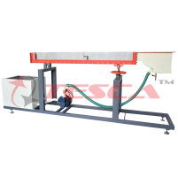
System Description: System Specifications:
Tesca Centrifugal Blower Test Apparatus enables the study of the performance of centrifugal blower (Compressor) & its calculation is the main focus in designing this trainer. The system has a Driving motor, Centrifugal Blower (Compressor), inlet & outlet ducts. The centrifugal blower & motor are mounted on a rigid stand. Measuring instruments are provided to measure Suction & Delivery pressure, Air Flow rate, Blower Speed, Motor Power Consumption. Tesca has designed the system having features of easy to operate; demonstrated & requisite experimentation can be performed.
Experiments Possibilities:
1. Calculation of centrifugal fan/blower performance. To determine volumetric Efficiency, Mechanical Efficiency.
Centrifugal blower: Discharge - 1500 CFM (Max.), Max. Pressure - 4 in of WC
Variable speed driven (optional computer- driven) Electric Motor: 0.5 HP, 3000 RPM with Speed controller
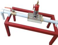
Aspiration transparent duct: Inner diameter:
114 mm. Includes a butterfly valve to regulate the airflow and an orifice plate with airflow measurement.
Discharge transparent duct: Inner diameter:
144 mm. Includes a butterfly valve to regulate the airflow.
Digital Multi-Function meter: Voltage; Current; Frequency & Wattage (optional computer interfaced readings)
Inductive Sensor & RPM Indicator: 0-9999RPM
1. Speed sensor, range: 0 - 3000 r.p.m.
2. Wattmeter.
3. Three differential pressure sensors to measure: The differential pressure in the aspiration duct.
4. The differential pressure in the discharge duct.
5. The air flows through the orifice plate; range:
-25 – 25 mm H2O.
6. To know the inlet air conditions:
7. “J” type temperature sensor. Pressure sensor, range: 0 – 1.1 atm.
8. Humidity sensor, range: 0 – 100 %.
9. Air Flow Measurement: Pitot Tube & Manometer or Anemometer
10. Manometer for Suction & Delivery pressure
11. Flow Control Valve.
12. Electrical switches & wiring
13. Frame & Control Panel: M.S. Square tubes & CR Sheet, duly powder coated.
14. Optional: impellers that can be offered:
15. Centrifugal pump impeller – forward curved, backward-curved, radial tipped, airfoil bladed, open type, or with shrouds.
16. Axial flow pump impeller
17. Mixed flow pump impeller
Computer Control Software:
18. PID Computer Control + Data Acquisition + Data Management.
19. Compatible with actual Windows operating systems. Graphic and intuitive simulation of the process on a screen. Compatible with the industry standards.
20. Registration and visualization of all process variables in an automatic and simultaneous way.
21. Flexible, open, and multi-control software, developed with actual windows graphic systems, acting simultaneously on all process parameters.
22. Analog and digital PID control.
23. Menu for PID and setpoint selection required in the whole work range.
24. Management, processing, comparison, and storage of data.
25. Sampling velocity up to 250 KS/s (Kilo samples per second).
26. Calibration system for the sensors involved in the process.
27. It allows the registration of the alarm state and the graphic representation in real-time.
28. Comparative analysis of the obtained data, after the process and modification of the conditions during the process.
29. Open software, allowing the teacher to modify texts, instructions. Teacher’s and student’s passwords facilitate the teacher’s control on the student and allowing access to different work levels.
30. This unit allows the 30 students of the classroom to simultaneously visualize all results and manipulation of the unit, during the process, by using a projector or an electronic whiteboard.
31. This module requires Control Interface Module and Data Acquisition.
Interface In-built Module:
This control interface is common for the ‘Tesca’ trainers and can work with one or several trainers. The Control Interface is part of the SCADA system.
Control interface with process diagram on the front panel.
The unit control elements are permanently computer-controlled.
Simultaneous visualization in the computer of all parameters involved in the process.
Calibration of all sensors involved in the process.
Real-time curves representation about system responses.
All the actuators’ values can be changed at any time from the keyboard allowing the analysis of curves and respons es of the whole process.
Shield and filtered signals to avoid external interferences.
Real-time PID control with flexibility of modifications from the computer keyboard of the PID parameters, at any moment during the process.
Real-time PID control for parameters involved in the process simultaneously.
Proportional control, integral control, and derivative control, based on the real PID mathematical formula, by changing the values, at any time, of the three control constants (proportional, integral, and derivative constants).
Open control allowing modifications, at any moment and in real-time, of parameters involved in the process simultaneously.
Three safety levels, one mechanical in the unit, another electronic in the control interface, and the third one in the control software.
Optional Accessories:
Digital sensors & indicators for Flow, Pressure
Data logging software
Cut Section Model of Centrifugal Blower
Torque Measurement
Operation & Maintenance Manual:
A self-explanatory operating & maintenance manual will be provided. This will include Theory, operating procedure, standard results, and maintenance procedures
Service Required At Site:
Electric Supply 230V 50Hz. With proper earthing.
Enquiry Form
Related Product
Tesca specialize in doing turnkey projects that is fully operable when it is handed over to the project authority. Starting from inception to application training, Tesca provides the services as ONE source solution. Working side by side with government authorities and people across the World, we help countries to perform better. We support countries grow their economies, strengthen their education and health systems and improve financial management. We do this by providing consultancy & training in environment safety, education, health strengthening.
Category
Useful Links
Contact Us
International Sales:
 91-9829132777
91-9413330765
India Sales:
91-9588842361
2026 © All Rights Reserved.