
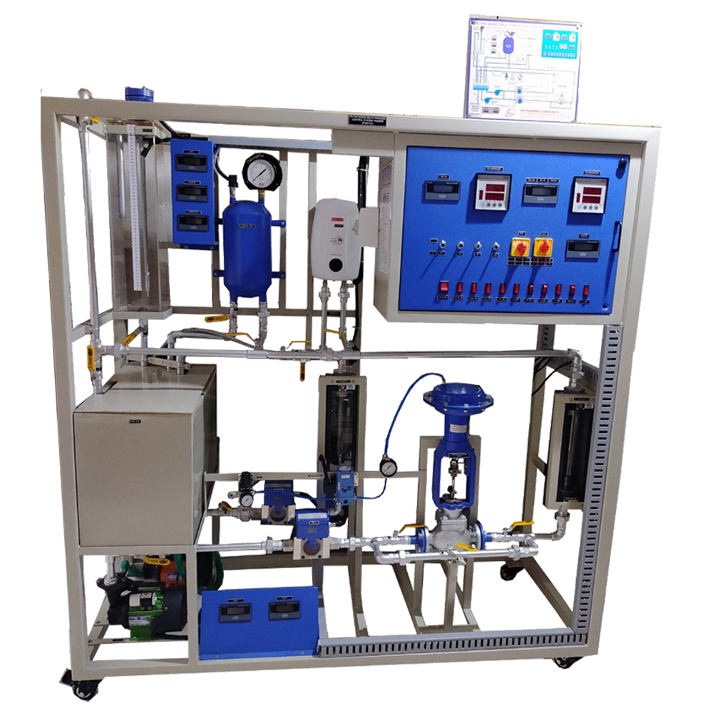
Control System Module
Order Code: 23246952.3
Category: General Lab Equipment II
Fundamentals of Automatic Control Technology Continuous Automatic Control -CAC Discontinuous Automatic Control -DAC Applications Temperature control -TEM ...
SPECIFICATION
|
Fundamentals of Automatic Control Technology |
|
Continuous Automatic Control -CAC Discontinuous Automatic Control -DAC |
|
Applications |
|
Temperature control -TEM |
|
FUNDAMENTALS OF AUTOMATIC CONTROL |
|
TECHNOLOGY Continuous Automatic Control - CAC |
|
Discontinuous Automatic Control - DAC |
|
The system must be composed of the following modules: |
|
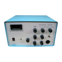
1. DC POWER SUPPLY Technical features: |
|
|
|
|
|
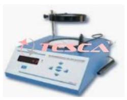
2. VOLTAGE REFERENCE GENERATOR |
|
Technical features: |
|
|
|
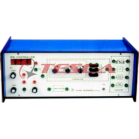
3. PID CONTROLLER |
|
Technical features: |
|
|
|
|
|
|
|
|
4. SUMMING POINT – 5 INPUTS |
|
Technical features: |
|
|
|
|
5. SIMULATED CONTROLLED SYSTEM |
|
Technical features: |
|
|
|
|
|
|
|
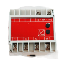
6. MANUAL/AUTOMATIC SWITCH |
|
Technical features: |
|
|
|
7. TWO POSITION CONTROLLER |
|
Technical features: |
|
|
|
|
|
|
8. POWER AMPLIFIER |
|
Technical features: |
|
|
|
|
|
|
|
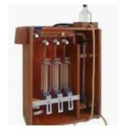
9. TEMPERATURE CONTROL SYSTEM |
|
Technical features: |
|
|
|
|
|
|
10. SINGLE POLE SWITCH |
|
This item shall consist in a plug-in element, normally open, with switch load 2 A, 250 V. It shall be contained in a plastic box and with a switch. |
|
11. SINGLE POLE PUSHBUTTON |
|
This item shall consist in a plug-in element, normally open, with switch load 2 A, 250 V. It shall be contained in a plastic box and with a push-button. |
|
12. P CONTROLLER |
|
Technical features : |
|
|
|
|
13. INTEGRAL-ACTION ELEMENT |
|
Technical features: |
|
|
|
|
14. DERIVATIVE-ACTION ELEMENT |
|
Technical features |
|
|
|
|
15. SUMMING POINT – 2 INPUTS |
|
Technical features |
|
|
|
|
16. DEAD TIME ELEMENT |
|
Technical features: |
|
|
|
|
|
17. SECOND ORDER TRANSFER ELEMENT |
|
Technical features: |
|
|
|
|
|
|
18. SAMPLE AND HOLD ELEMENT |
|
Technical features: |
|
|
|
|
19. TEST FUNCTION GENERATOR |
|
Technical features: |
|
|
|
|
|
|
|
|
|
20. GAIN AND OFFSET ADJUST |
|
Technical features: |
|
|
|
|
|
|
|
|
21. SOFTWARE |
|
This software shall have a multiple control window: |
|
|
|
|
|
22. COMPUTER INTERFACE |
|
|
|
23. Connecting Leads |
|
|
24. Three-level Frame |
|
|
Standard Accessories: The equipment / instrument which are required to carry out the required experiment should come under standard accessories. The following accessories should be supplied along with this equipment: o Storage case/box |
Enquiry Form
Related Product


Tesca specialize in doing turnkey projects that is fully operable when it is handed over to the project authority. Starting from inception to application training, Tesca provides the services as ONE source solution. Working side by side with government authorities and people across the World, we help countries to perform better. We support countries grow their economies, strengthen their education and health systems and improve financial management. We do this by providing consultancy & training in environment safety, education, health strengthening.
Category
Useful Links
Contact Us
International Sales:
 91-9829132777
91-9413330765
India Sales:
91-9588842361
2026 © All Rights Reserved.