
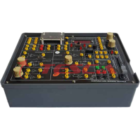
DC Position Control System
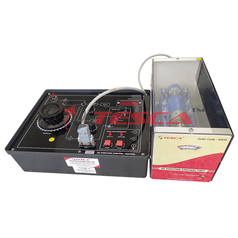
Order Code: 52030
Category: Instrumentation Trainers
Compact system - no mechanical hassles Simplified operation mP based storage of response mPositive/ Negative tachogenerator feedback Introduction One of the most common examples covered in text books and literature on linea...
SPECIFICATION
- Compact system - no mechanical hassles
- Simplified operation
- mP based storage of response
- mPositive/ Negative tachogenerator feedback
Introduction
One of the most common examples covered in text books and literature on linear systems is a d.c. position control system. This system is easily understood and has a second order transfer function in the standard form, for which a well developed theoretical treatment is available.
This unit provides the students an opportunity to study and operate a practical electromechanical angular-position-control system. The system is built around a good quality permanent magnet armature-controlled d.c. motor, speed reduction gear-set, potentiometric error detector using special 360° revolution servo potentiometers, a tachogenerator for velocity feedback and associated electronic circuits. Unlike simulated systems, e.g. our LINEAR SYSTEM SIMULATOR, the position control system naturally consists of non-ideal parameters viz. saturation of amplifier and motor current, dead zone and backlash, nonlinearity in the motor and gears, imperfections in mechanical fabrication and somewhat uncertain order of the complete system due to filters, various time constants and load parameters. Experimental work on this system would enable the students to appreciate the difference in performance between idealized systems studied in the theory classes
and the systems encountered in practice.
A difficulty which is faced while working with many practical control systems is that their responses are rather slow (Note that in a simulated system the common practice is to scale-up the frequency to ensure a proper viewing on a CRO). A storage CRO or an X-Y plotter is therefore required for studying the waveforms. Both these instruments are too expensive and/or delicate, and are therefore not usually available to the undergraduate students in most institutions. The present unit has a built-in mP based waveform capture/display system which stores the step response of the control system in a RAM and then displays it on a measuring CRO for further studies. This arrangement is extremely simple to operate and conforms to the accuracy needs of a class room experiment. The motor unit is housed in a separate cabinet with transparent panels for easy viewing. Interconnection with the main unit is through a standard 9-pin D-type connector. All power supplies and step input signal are internally provided. In addition a 3½ digit DVM is available on the panel for the measurement of various signals. A good quality measuring CRO is the only accessory that would be required.
Experiments
- Operation of the position control system for different values of the forward gain to angular position commands
- Step response studies for various values of forward gain
- Study of the effect of velocity feedback on the transient and steady state performance of the
- system as well as its stability
The experiments would involve calibration and operation of the waveform capture/display section as a first step. It may be mentioned here that due to the non-linearities and other imperfections and uncertainties existing in a physical system of the present type, a quantitative verification of the results with theoretical analysis is not recommended. This is best done on a simulated system. Of course the experimental work does include determination of rise time, overshoot, steady state errors etc. for various conditions for an evaluation of the system performance.
Feature and Specifications
- Position control of a 12V, 1A d.c. gear motor (50 rpm)
- Provision for positive and negative tachogenerator feedback
- Tacho constant: 2V/1000 rpm approximately
- Calibrated dials for reference and output position: resolution 1°
- Servo-potentiometers with full 360° rotation
- mP based waveform capture/display card
- Built-in 3½ digit DVM for signal measurements
- Built-in step signal and IC regulated power supplies for electronic circuits
- Separate unit for motor in a see-through cabinet
- 220V±10%, 50Hz mains operation
- Literature and patch cords included
- Essential accessories - a CROFeatures and Specifications
Enquiry Form
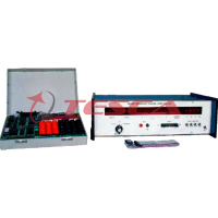
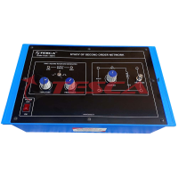
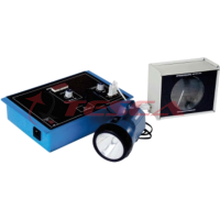
Related Product


Tesca specialize in doing turnkey projects that is fully operable when it is handed over to the project authority. Starting from inception to application training, Tesca provides the services as ONE source solution. Working side by side with government authorities and people across the World, we help countries to perform better. We support countries grow their economies, strengthen their education and health systems and improve financial management. We do this by providing consultancy & training in environment safety, education, health strengthening.
Category
Useful Links
Contact Us
International Sales:
 91-9829132777
91-9413330765
India Sales:
91-9588842361
2026 © All Rights Reserved.