
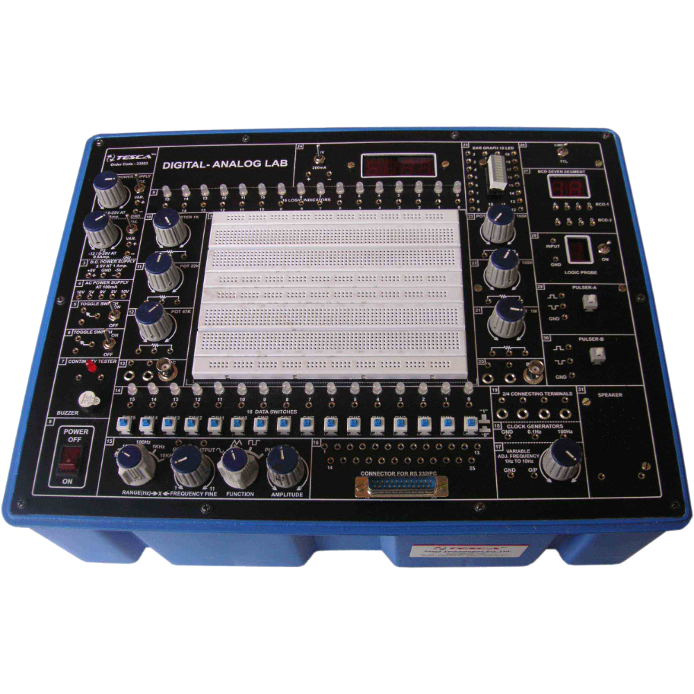
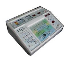
Digital- Analog Electronics Training System
Order Code: 19204644.12
Category: General Lab Equipment III
The trainer should consist of the following: A Solderless breadboard : AD-222Interconnected with 2712 tie points nickel plated contact, fits all components with DIP sizes and solid wireAWG #22-30(0.3 0.8mm) that can be changed and replaced for ...
SPECIFICATION
The trainer should consist of the following:
- A Solderless breadboard : AD-222Interconnected with 2712 tie points nickel plated contact, fits all components with DIP sizes and solid wireAWG #22-30(0.3 0.8mm) that can be changed and replaced for different purpose and can be connected with demonstration panel.
- DC power supply :
- Fixed DC output : +5V, 1A.
- Fixed DC output : -5V, 300mA.
- Variable DC output : 0V ~ +15V, 500mA.
- Variable DC output : 0V ~ -15V, 500mA.
- Potentiometers :
- Variable resistor VR1 = 1 KΩ (B)
- Variable resistor VR2 = 100KΩ (B)
- Function generator
- Frequency ranges : 1 Hz ~ 10 Hz
- 10 Hz ~ 100 Hz
- 100 Hz ~ 1 K Hz
- 1K Hz ~ 10K Hz
- 10K Hz ~ 100K Hz
- Amplitude Sine wave output : 0 ~ 8 Vpp variable
- Triangle wave output : 0~6 Vpp variable
- Square wave output : 0~8 Vpp variable
- TTL mode output : 0 ~+5V
- Eight bits data switches :
- When toggle switch is set at "down" position, the output is LO level;
- on the contrary, it will be HI level while setting at "up" position.
- Speaker : 2½ inch diameter 8ohm/0.25W to be used for load
- Four channel adaptor :Ttwo banana sockets' and two BNC jacks' point tips to be changeable.
- Two digits of segment LED display : Output display
- Numerical designs and resultant displays
- Two pulse switch (with 2 sets of output: A, A, B, B):
- 8 bits LED display: Eight red LED's separate input terminals.
- The LED will be lighted up when input is at "HI level", and it will be turned off when it is at no input or at "LO level".
- Universal connector fixed holder: Standard accessory :
- UC-03 Straight header 60pin Optional accessories :
- UC-01 : Card edge connector 2.54 mm 62pin
- UC-02 : RS-232 connector 25pin D sub connector, male & female
- UC-04 : Card edge connector 3.96 mm 56pin To be supplied with the following
- accessories: Analog Overlay Learning System
- Circuit diagram (tracing paper) : 28pcs for atleast 28 different analog circuits assembly experiments
- Experiment book : 1pc
- Components : 1set
- RM-203 breadboard : 1pc
- Digital Overlay Learning System
- Circuit diagram (tracing paper) : 62pcs for atleast 62 different digital circuits assembly experiments
- Experiment book : 1pc
- Components : 1set
- RM-203 breadboard : 1pc
- Dimensions : 290 x 225 x 55
Enquiry Form
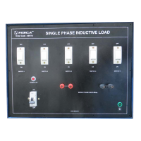
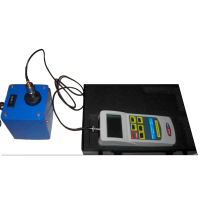
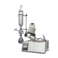
Related Product

Tesca specialize in doing turnkey projects that is fully operable when it is handed over to the project authority. Starting from inception to application training, Tesca provides the services as ONE source solution. Working side by side with government authorities and people across the World, we help countries to perform better. We support countries grow their economies, strengthen their education and health systems and improve financial management. We do this by providing consultancy & training in environment safety, education, health strengthening.
Category
Useful Links
Contact Us
International Sales:
 91-9829132777
91-9413330765
India Sales:
91-9588842361
2026 © All Rights Reserved.