
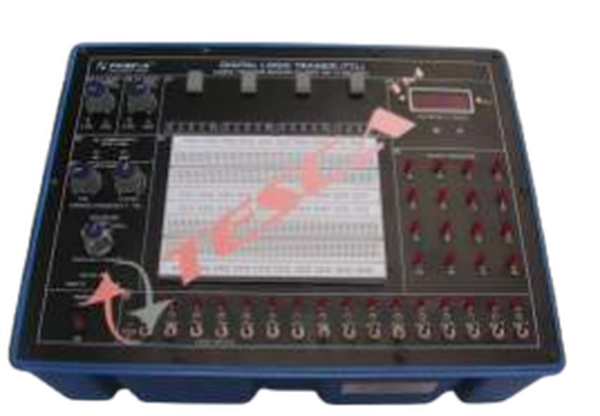
Digital Logic Circuit Trainer
Order Code: 23246299.6
Category: General Lab Equipment II
Module One: Chapter 1: Basic Logic Gates Circuits Experiment 1: Logic Gates Structure Circuits (DL, RTL, TTL, CMOS) Input Data Length: 2 bits; Input Data Mode: Dip Switch Experiment 2: Logic Gates Circuits Include Logic Gates: AND Gate;...
SPECIFICATION
Module One:
- Chapter 1: Basic Logic Gates Circuits
- Experiment 1: Logic Gates Structure Circuits (DL, RTL, TTL, CMOS)
- Input Data Length: 2 bits; Input Data Mode: Dip Switch
- Experiment 2: Logic Gates Circuits
- Include Logic Gates: AND Gate; NANO Gate; NOT Gate; OR Gate; NOR Gate; XOR Gate
- Experiment 3: Voltage and Current Measurement (TTL, CMOS)
- Voltage Measurement: VIH, VIL, VOH, VOL; Current Measurement: IOH, IOL
- Experiment 4: Interface between Logic Gates Circuits (TTL and CMOS Transform)
- TTL to CMOS Transform: Input: 5 V; Output: 12 V; CMOS to TTL Transform: Input: 12 V; Output: 5 V
- Experiment 5: Transmission Delay Measurement (TTL, CMOS)
- TTL Transmission Delay: 20.8 nS; CMOS Transmission Delay: 99.1 nS
Module Two:
- Chapter 2 Combinational Logic Circuits
- Experiment 1: 4 Bits Comparator Circuit
- Input Data Length: 4 bits; Input Data Mode: Dip Switch; Output Data Length: 3 bits; Data Display Mode: LED Display
- Experiment 2: 9 Bits Parity Generator
- Input Data Length: 9 bits; Input Data Mode: Dip Switch; Output Data Length: 2 bits; Data Display Mode: LED Display
- Experiment 3: Tristate and Schmitt Gate Circuits
- Tristate Gate: Data Length: 1 bits; Input Data Mode: Dip Switch; Schmitt Gate: Measurement VIH, VIL, VOH, VOL
- Experiment 4: Half Adder and Full Adder
- Half Adder: Input Data Length: 2 bits; Input Data Mode: Dip Switch
- Output Data Length: 2 bits; Data Display Mode: LED Display
- Full Adder: Input Data Length: 3 bits; Input Data Mode: Dip Switch
- Output Data Length: 2 bits; Data Display Mode: LED Display
- Experiment 5: Half Subtracter and Full Subtracter
- Half Subtracter: Input Data Length: 2 bits; Input Data Mode: Dip Switch
- Output Data Length: 2 bits; Data Display Mode: LED Display
- Full Subtracter: Input Data Length: 3 bits; Input Data Mode: Dip Switch
- Output Data Length: 2 bits; Data Display Mode: LED Display
Module Three:
- Chapter 3: Extended Combinational Logic Circuits
- Experiment 1: Arithmetic Logic Unit (ALU) Circuit
- Input Data Length: 4 bits; Input Data Mode: Dip Switch
- Output Data Length: 4 bits; Data Display Mode: LED Display; Operation instruction: 16 Types
- Experiment 2: Encoder Circuit
- Input Data Length: 8 bits; Input Data Mode: Dip Switch; Output Data Length: 3 bits; Data Display Mode: LED Display
- Experiment 3: Decoder Circuit
- Input Data Length: 3 bits; Input Data Mode: Dip Switch; Output Data Length: 8 bits; Data Display Mode: LED Display
- Experiment 4: Multiplexer Circuit
- Input Data Length: 4 bits; Input Data Mode: Dip Switch
- Output Data Length: 1 bits; Data Display Mode: LED Display
- Experiment 5: Demultiplexer Circuit
- Input Data Length: 1 bits; Input Data Mode: Dip Switch; Output Data Length: 4 bits; Data Display Mode: LED Display
- Experiment 6: Digitally Controlled Analog Multiplexer and Demultiplexer Circuits
- Multiplexer: Input Voltage: 0 V ~ 5 V; Input Quantity: 2; Output Voltage: 0 V ~ 5 V; Output Quantity: 1
- Demultiplexer: Input Voltage: 0 V ~ 5 V; Input Quantity: 1; Output Voltage: 0 V ~ 5 V; Output Quantity: 2
Module Four:
- Chapter 4: Clock Generator Circuit
- Experiment 1: Constructing Oscillator Circuit with Basic Logic Gates and Schmitt Gates
- Basic Logic Oscillator: Output Frequency: 3.58 MHz; Schmitt Gates Oscillator: Output Frequency: 3.58 MHz
- Experiment 2: Voltage Controlled Oscillator Circuit (Output Frequency: 26.8 kHz ~ 35.5 kHz)
- Experiment 3: BJT Astable Multivibrator Oscillator Circuit (Output Frequency: 160 kHz)
- Experiment 4: Operational Amplifier Oscillator Circuit (Output Frequency: 2.56 kHz)
- Experiment 5: 555 Astable Multivibrator and Monostable Multivibrator Oscillator
- Astable Multivibrator: 4.75 Hz; Monostable Multivibrator: User Controlled
Enquiry Form
Related Product


Tesca specialize in doing turnkey projects that is fully operable when it is handed over to the project authority. Starting from inception to application training, Tesca provides the services as ONE source solution. Working side by side with government authorities and people across the World, we help countries to perform better. We support countries grow their economies, strengthen their education and health systems and improve financial management. We do this by providing consultancy & training in environment safety, education, health strengthening.
Category
Useful Links
Contact Us
International Sales:
 91-9829132777
91-9413330765
India Sales:
91-9588842361
2026 © All Rights Reserved.