
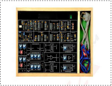
Digital Logic Circuits Trainer with Eight Module and Function Generator & DC Power Supply

Order Code: 25269126.7
Category: General Lab Equipment V
Technical Specification: The Digital Logic Circuits Trainer should consist of following eight modules with Function Generator and DC Power Supply: Module One: Chapter 1: Basic Logic Gates Circuits Experiment 1: Logic Gates Structur...
SPECIFICATION
Technical Specification:
The Digital Logic Circuits Trainer should consist of following eight modules with Function Generator and DC Power Supply:
Module One:
-
Chapter 1: Basic Logic Gates Circuits
-
Experiment 1: Logic Gates Structure Circuits (DL, RTL, TTL, CMOS)
-
Input Data Length: 2 bits; Input Data Mode: Dip Switch
-
Experiment 2: Logic Gates Circuits
-
Include Logic Gates: AND Gate; NAND Gate; NOT Gate; OR Gate; NOR Gate; XOR Gate
Experiment 3: Voltage and Current Measurement (TTL, CMOS)
Voltage Measurement: VIH, VIL, VOH, VOL; Current Measurement: IOH, IOL -
Experiment 4: Interface between Logic Gates Circuits (TTL and CMOS Transform)
TTL to CMOS Transform: Input: 5 V; Output: 12 V; CMOS to TTL Transform: Input: 12 V; Output: 5 V -
Experiment 5: Transmission Delay Measurement (TTL, CMOS)
TTL Transmission Delay: 20.8 nS; (Maximum) CMOS Transmission Delay: 99.1 nS (Maximum)
Module Two:
-
Chapter 2 Combinational Logic Circuits
-
Experiment 1: 4 Bits Comparator Circuit
-
Input Data Length: 4 bits; Input Data Mode: Dip Switch; Output Data Length: 3 bits; Data Display Mode: LED Display
-
Experiment 2: 9 Bits Parity Generator
Input Data Length: 9 bits; Input Data Mode: Dip Switch; Output Data Length: 2 bits; Data Display Mode: LED Display -
Experiment 3: Tristate and Schmitt Gate Circuits
Tristate Gate: Data Length: 1 bit; Input Data Mode: Dip Switch; Schmitt Gate: Measurement VIH, VIL, VOH, VOL -
Experiment 4: Half Adder and Full Adder
Half Adder: Input Data Length: 2 bits; Input Data Mode: Dip SwitchOutput Data Length: 2 bits; Data Display Mode: LED Display
Full Adder: Input Data Length: 3 bits; Input Data Mode: Dip SwitchOutput Data Length: 2 bits; Data Display Mode: LED Display
Experiment 5: Half Subtracter and Full Subtracter Half Subtracter: Input Data Length: 2 bits; Input Data Mode: Dip Switch Output Data Length: 2 bits; Data Display Mode: LED Display
Full Subtracter: Input Data Length: 3 bits; Input Data Mode: Dip Switch Output Data Length: 2 bits; Data Display Mode: LED Display
Module Three:
Chapter 3: Extended Combinational Logic Circuits
-
Experiment 1: Arithmetic Logic Unit (ALU) Circuit Input Data Length: 4 bits; Input Data Mode: Dip Switch
-
Output Data Length: 4 bits; Data Display Mode: LED Display; Operation instruction: 16 Types
-
Experiment 2: Encoder Circuit Input Data Length: 8 bits; Input Data Mode: Dip Switch; Output Data Length: 3 bits; Data Display Mode: LED Display
Experiment 3: Decoder Circuit Input Data Length: 3 bits; Input Data Mode: Dip Switch; Output Data Length: 8 bits; Data Display Mode: LED Display
Experiment 4: Multiplexer Circuit Input Data Length: 4 bits; Input Data Mode: Dip Switch -
Output Data Length: 1 bits; Data Display Mode: LED Display
Experiment 5: Demultiplexer Circuit Input Data Length: 1 bits; Input Data Mode: Dip Switch; Output Data Length: 4 bits; Data Display Mode: LED Display
Experiment 6: Digitally Controlled Analog Multiplexer and Demultiplexer Circuits
Multiplexer: Input Voltage: 0 V ~ 5 V; Input Quantity: 2; Output Voltage: 0 V ~ 5 V; Output Quantity: 1
Demultiplexer: Input Voltage: 0 V ~ 5 V; Input Quantity: 1; Output Voltage: 0 V ~ 5 V; Output Quantity: 2
Module Four:
Chapter 4: Clock Generator Circuit
-
Experiment 1: Constructing Oscillator Circuit with Basic Logic Gates and Schmitt Gates
Basic Logic Oscillator: Output Frequency: 3.58 MHz; Schmitt Gates Oscillator: Output Frequency: 3.58 Mhz -
Experiment 2: Voltage Controlled Oscillator Circuit (Output Frequency: 26.8 kHz ~ 35.5 kHz)
-
Experiment 3: BJT Astable Multivibrator Oscillator Circuit (Output Frequency: 160 kHz)
Experiment 4: Operational Amplifier Oscillator Circuit (Output Frequency: 2.56 kHz)
Experiment 5: 555 Astable Multivibrator and Monostable Multivibrator Oscillator
Astable Multivibrator: 4.75 Hz; Monostable Multivibrator: User Controlled
Module Five:
Chapter 5: Sequential Logic Circuits
Experiment 1: RS Flip-flop Circuit
Input Data Length: 2 bits; Input Data Mode: Dip Switch; Output Data Length: 1 bits; Data Display Mode: LED Display
Experiment 2: JK Flip-flop Circuit
Input Data Length: 2 bits; Input Data Mode: Dip Switch; Output Data Length: 2 bits; Data Display Mode: LED Display
Experiment 3: D Flip-flop Circuit
Input Data Length: 1 bits; Input Data Mode: Dip Switch; Output Data Length: 2 bits; Data Display Mode: LED Display
Experiment 4: Asynchronous Counter Circuit
Output Data Length: 4 bits; Data Display Mode: LED Display
Experiment 5: Synchronous Counter Circuit
Input Data Mode: Dip Switch; Output Data Length: 5 bits; Data Display Mode: LED Display
Experiment 6: Presetably Synchronous Counter Circuit
Presetably Data Length: 4 bits; Input Data Mode: Dip Switch
Output Data Length: 5 bits; Data Display Mode: LED Display; Count Mode: Up Count or Down Count
Module Six:
Chapter 6: Memory Circuits
Experiment 1: Constructing ROM Circuit with Diodes
Store Data Length: 2 bits; Data Display Mode: LED Display
Experiment 2: Constructing RAM Circuit with D Flip-flop
Input Data Length: 4 bits; Input Data Mode: Dip Switch; Output Data Length: 4 bits; Data Display Mode: LED Display
Experiment 3: Programable ROM Circuit
Experiment 4: 64 Bits RAM Circuit
Input Data Length: 4 bits; Input Data Mode: Dip Switch; Output Data Length: 4 bits; Data Display Mode: LED Display
Module Seven:
Chapter 7: Converter Circuits
Experiment 1: OPA ADC Circuit
Analog Input: 0 V-5 V; Data Display Mode: LED Display; Resolution: 4 bits
Experiment 2: ADC0804 ADC Circuit
Analog Input: 0 V-5 V; Data Display Mode: LED Display; Resolution: 8 bits
Experiment 3: 4 Bits R-2R DAC Circuit (Digital Input: 4 bits; Analog Output: 0 V-5 V)
Experiment 4: Unipolar DAC0800 DAC Circuit
Digital Input: 8 bits; Input Data Mode: Dip Switch; Analog Output: 0 V - 5 V; Step Value: 0.019 V
Experiment 5: Bipolar DAC0800 DAC Circuit
Digital Input: 8 bits; Input Data Mode: Dip Switch; Analog Output: -5 V - 5 V; Step Value: 0.038 V
Module Eight:
Chapter 8: Logic Application Circuits
Experiment 1: Electronic Voting Circuit (7408, 7404, 7432, 7486)
Experiment 2: Electronic Wheel-amusement Circuit (Vcc= 12 V; IC: 555, CD4017B)
Experiment 3: Electronic Competition-answer Circuit (Vcc= 12 V; IC: CD4011 B)
Experiment 4: Traffic Light Circuit (Vcc= 12V; IC:555, CD4017B)
Function Generator & DC Power Supply Module:
-
Waveforms: Sine, Triangle, Square, TTL Pulse
-
Amplitude: >10 Vpp
-
Impedance: 50Ω ±10%
-
Duty Control: 30% ~ 60%
-
Display: 6-Digit LED Display
-
Frequency Range: 10Hz to 100 kHz (4 Ranges), 100Hz to 1 MHz (4 Ranges)
-
Frequency Control: Separative Coarse and Fine Tuning
-
Constant Voltage Output: ±5V, ±12V
-
Variable Voltage Output: 0V ~ ±15V
-
Power source: 220V AC ±10%, 50Hz
Enquiry Form
Related Product


Tesca specialize in doing turnkey projects that is fully operable when it is handed over to the project authority. Starting from inception to application training, Tesca provides the services as ONE source solution. Working side by side with government authorities and people across the World, we help countries to perform better. We support countries grow their economies, strengthen their education and health systems and improve financial management. We do this by providing consultancy & training in environment safety, education, health strengthening.
Category
Useful Links
Contact Us
International Sales:
 91-9829132777
91-9413330765
India Sales:
91-9588842361
2026 © All Rights Reserved.