
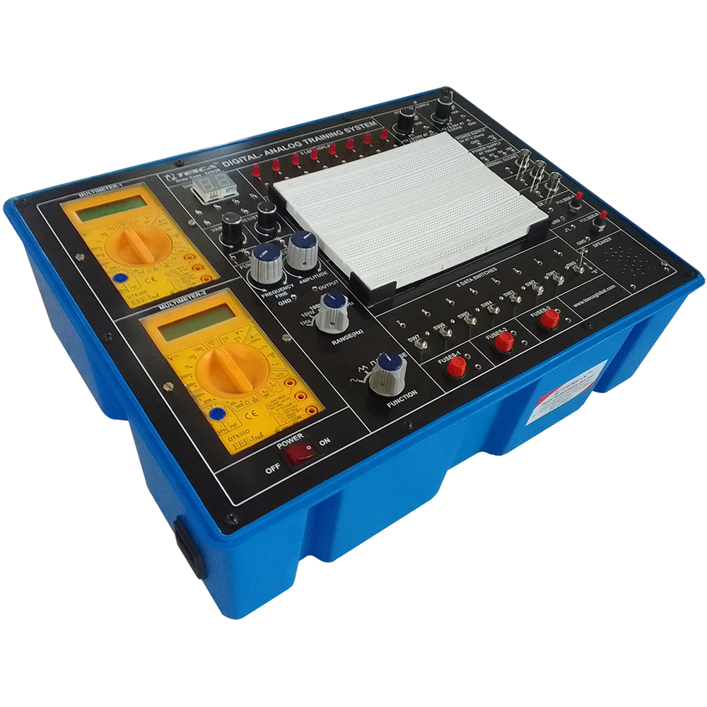
Digital Logic Lab Part-01
Order Code: 23246836.8
Category: General Lab Equipment III
Features Suitable for combination logic, sequential logic and microprocessor circuits design and experiments Ideal tool for learning the basics of digital logic circuits Comprehensive power, signal supply and testing devices for convenient experimen...
SPECIFICATION
Features
Suitable for combination logic, sequential logic and microprocessor circuits design and experiments Ideal tool for learning the basics of digital logic circuits Comprehensive power, signal supply and testing devices for convenient experiments Experiments are expandable and flexible with universal breadboard Capable of processing TTL, CMOS, NMOS, PMOS and ECL circuits All supply units are equipped with overload protection for safety purpose.
All modules equipped with 8-bit DIP switch for fault simulations Individual keeping cases for all modules for easy storing and carrying All signal generators have independent and simultaneous TTL and CMOS level output terminal.
Specifications:
Main Unit
1. Dual DC Power Supply
(1) Voltage range : +5V/1.5A, -5V/0.3A, ?12V/0.3A
(2) With output overload protection
2. Adjustable DC Power Supply
(1) Voltage range : +1.5V ~ +15V
(2) Max. current output : 0.5A
(3)With output overload protection
3. Standard Frequency
(1) Frequency : 1MHz, 60Hz, 1Hz
(2)Accuracy : Set 02 576000 1152000
(3)Fan out : 10 TTL load
4. Clock Signal Generator
(1) Frequency : 1Hz ~ 1MHz (6 ranges)
a.1Hz ~ 10Hz
b.10Hz ~ 100Hz
c.100Hz ~ 1KHz
d.1KHz ~ 10KHz
e. 10KHz ~ 100KHz
f. 100KHz ~ 1MHz
(2) Fan out : 10 TTL load
5. Data Switch
(1) 8-bit DIP switch x 2, 16-bit TTL level output
(2) Toggle switch x 4, each withDebouncecircuit
(3) Fan out : 10 TTL load
6. Pulser Switch
(1) 2 sets of independent control output
(2) Each set with Q, Q' output, pulse width > 5ms
(3) Each set of switch with Debounce circuit
(4) Fan out : 10 TTL load
7. Line Signal Generator
(1) Frequency : 50Hz/60Hz
(2) Output voltage : 6Vrms
(3) With overload protection
8. Thumbwheel Switch : 2-digit, BCD code output and common point input
9. Logic Indicator
(1) 16 sets of independent LED indicates high /low logic state
(2) Input Impedance : ≥ 100K ohms
10. Digital Displays
(1) 4 sets of independent 7-segment LED display
(2) With BCD, 7-segment decoder/driver and DP input
(3) Input with 8-4-2-1 code
11. Logic Probe
(1) TTL and CMOS level
(2) 5mm LED displays
(3) ''Lo'' and ''Hi'' LED display low/high logic state respectively
12. Speaker : 8 ohms, 0.25W speaker with driver circuit
13. Breadboard Modules: 1680 tie-point breadboard on top panel can be easily put into and taken off.
Experiment Modules
1. All 13 modules are equipped with an 8-bit DIP switch for fault simulation. Users learn how to solve various. Problems by setting the DIP switch to different positions.
2. Solutions for all fault test are listed in the experiment manual for user's reference.
3. 2mm plugs and sockets are used throughout the main unit and all modules.
4. Comprehensive experiment manual and instructor's manual.
5. Module dimension: (255 x 165 x 30) mm.
6. Connection plugs are used on the modules to prevent accidental damages.
7. Individual keeping case for each module.
Enquiry Form
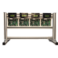
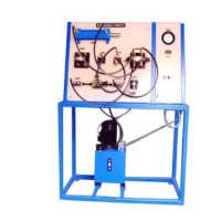
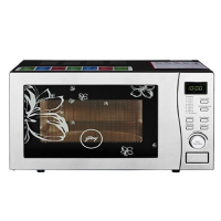
Related Product


Tesca specialize in doing turnkey projects that is fully operable when it is handed over to the project authority. Starting from inception to application training, Tesca provides the services as ONE source solution. Working side by side with government authorities and people across the World, we help countries to perform better. We support countries grow their economies, strengthen their education and health systems and improve financial management. We do this by providing consultancy & training in environment safety, education, health strengthening.
Category
Useful Links
Contact Us
International Sales:
 91-9829132777
91-9413330765
India Sales:
91-9588842361
2026 © All Rights Reserved.