
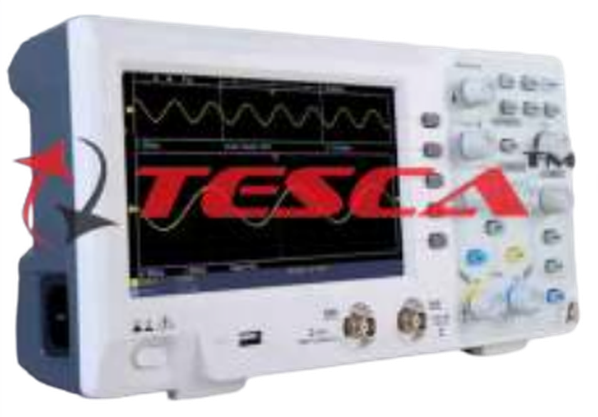
Digital Storage Oscilloscope
Order Code: 23246295.2
Category: General Lab Equipment II
- This system should be a combination of hardware and software - Data collection and analysis should be available from the software window - Frequency range: 914 MHz and 2.45 Ghz - Output power: +4.5 dBm or better - Local oscillation: PLL ...
SPECIFICATION
- This system should be a combination of hardware and software
- Data collection and analysis should be available from the software window
- Frequency range: 914 MHz and 2.45 Ghz
- Output power: +4.5 dBm or better
- Local oscillation: PLL
- Impedance: 50?
- AGC dynamic range: 40dB
- IF: 20.0 ~ 22.0 MHz
- Antennas: Yagi, Chip, Dipole, Monopole, Loop, Patch, Inverted F and Array Patch
- Control method: Micro-controller
- Antenna angle control: 360°, 400 steps (0.9° / steps)
- Position calibration: Auto calibration
- Motor rotation: Front, Back, Step
- User interface in GUI environment
- Simulation as well emulation should be available
- The system should be configured with Transmitting antennas with RF transmitter, Receiving antennas with RF Receiver, Motor control, Software system etc.
- The RF Generator should have following terminals:
- RF (914MHz and 2.45GHz) output and input terminals
- Output terminal for phase delay and power attenuation experiment: Output terminal for an original signal or direct receivingpath, output terminal for receiving path 1 & 2 and Summed output terminal for each path
- Output terminal for VSW experiment: Incidence wave and Reflection wave
- Output terminal for time delay fading experiment: Output terminal for an original signal wave form and time delayed wave form with delay time selection switch/knob
- Should have present experiment indicating LED, Power switch and reset switch
- The software's main menu toolbar should consist of following icons:
- Radiation Pattern measuring experiment icon
- Voltage Standing Wave measuring experimenticon
- PhaseDelay experimenticon
- Attenuationcharacteristicsexperiment icon
- Multi Path Fading experiment icon
- Doppler Frequency experiment icon
- Time Delay experiment icon
- Hata Model propagation loss experiment and Program exit icon
- The experiment screen toolbar should have calibration, frequency selection and main screen return functions
- Power source: 220~230V AC, 50Hz, 1 Phase Components to be supplied:
- Antennas & training antennas, Antenna bases, Antenna fixing brackets, Carriage bag, Cables, Adaptor, Wrench, Program CD;
Enquiry Form
Related Product

Tesca specialize in doing turnkey projects that is fully operable when it is handed over to the project authority. Starting from inception to application training, Tesca provides the services as ONE source solution. Working side by side with government authorities and people across the World, we help countries to perform better. We support countries grow their economies, strengthen their education and health systems and improve financial management. We do this by providing consultancy & training in environment safety, education, health strengthening.
Category
Useful Links
Contact Us
International Sales:
 91-9829132777
91-9413330765
India Sales:
91-9588842361
2026 © All Rights Reserved.