
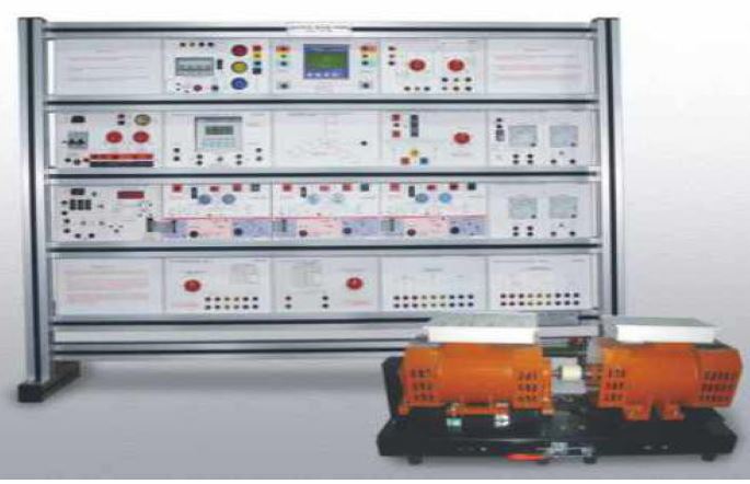
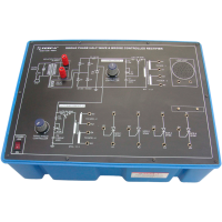
Electrical Machines Trainer
Order Code: 20214413.1
Category: General Lab Equipment III
Features : Should have 4mm sturdy shrouded banana patch cords & shrouded arrangements. All machines should be mounted on finely painted sturdy base frame with easy machine interchangeability. Should be able to dr...
SPECIFICATION
Features :
- Should have 4mm sturdy shrouded banana patch cords & shrouded arrangements.
- All machines should be mounted on finely painted sturdy base frame with easy machine interchangeability.
- Should be able to draw all graphs
- Machines should operate upto 300W power levels & upto 1500 RPM.
- Must use Trunnion mounted DC machine as Dynamometer for loading other machines with facility to measure shaft power using electronic torque / speed measurement
- One Dynamometer type DC ink per aluminum Rack with multiple panels
A) Technical Specifications of interfacing panel rack -
- 1 No. Powder coated Sturdy aluminums Flat panel system made up of Alluminium extruded profiles carrying various high voltage components housed in plastic enclosures to minimize shock possibility. Should be able to hold following control panels with colorful overlay.
- Trainer should be modular panels fel easy site servicing not close controlt-panel box no wiring should not be there & shrouded 4 mm banana patch cords & shrouded sockets arrangements for the safety of the students
B) Each control panel rack consists of Input 3 phase DOL Starter panel [10 Shrouded Banana] 1 No.
- 4 pole MCB of 415 V/4A
- DOL 9A Contactor with 230V / 50 1-1z / I IVA COIL .
- Bimetallic thermal 0/L relay with range I .4A - 2.3A .
- Integrated AC (1 phase) measurement panel 1 No. Bidirectional Multifunction Meter
- 3 Phase 3/4 wire, 415V, CT Input 5A
- LCD/LED display, Aux supply 230V, 45-65 Hz, 5W 'VI, Hz, Pf, KVA, KW,KWH Modbus RTU RS 485
- 3 Ph. Bidirectional power cum Energy meter panel --1 No.
- Bidirectional Multifunction
- 3 Phase % wire, 415V, CT Input 5A
- LCD/LED 'display, Aux supply 230V, 45-65 Hz, 5W • V,I., Hz, Pf, KVA, KW,KWH
- Modbus RTU RS 485 FWD/REV, Star-Delta starter panel --1 No.
- FWD/REV, 3 pole 3 way switch with centre OFF, 6A/440V.
- Star/Delta switch 3 pole, 3 way with centre OFF, 6A/440V. 3 Phase wound Rotor & Sync. Motor panel --1 No.
- Rotor resistors of 30E/5A with 3 taps of 15E, 21E, 30E each - 3 Nos.
- Rotor resistor selector switch, 3 pole. 6Way 6A/440V.
- DC Rotor excitation with circuit breaker (3Amp)
- ph. Motor, Alternator & Sync. Motor Panel
- I ph. MCBs of 4A/1.6A 1 each.
- 2 no. 2P2W selector switches to run as 1 ph. alternator then as synchronous motor.
- 8A pushbutton switch to simulate as centrifugal switch.
- I No. lamp holder with input sockets DC voltmeter & DC ammeter panel 2 Nos.
- DC voltmeter(0-300V)
- DC Ammeter (0-5A) with polarity protection diode
- Field failure relay to control A nnature supply.
- 4A Circuit Breaker.
- SCR Actuator (variable DC) cum sensor signal conditioning panel
- 3 Nos
- Full bridge SCR based OV-195V / 3 Amp cosine firing with linear characteristics.
- Supports signal conditioning circuit for speed, torque in kg. to give output 0- 2.5Vdc (FS).
- 3 Nos. of these supplies required for DC Armature, DC motor field & AC generator field.
- Instrumentation Power supply cum Multichannel DPM panel I No.
- (a) DC Multi Output power supply
- (b) Supplies DC power to neighboring signal conditioning circuit panels like EMT9, CIPI, 2, MITI2, CE7 etc. through 20 pin FRC cable.
- (c) Provides I Ph. AC supply through 3 MCB's, 4A each to power up lather panels in the rack
- (d) Multichannel DPM for digital display of torque, speed etc. Resistor Load Panel 1 No.
- Should have off position to run on no load.
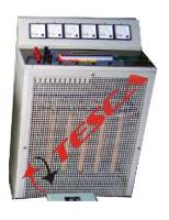
- (1)AC Resistors = 10K/200 WX3 phases/ 6 steps
- (2) DC Resistors = 750E/400W / 6 steps
- LC Load panel 1 No.
- (A) Inductive load = 0.1 5H/0.311/0.45H/0.6H/0.75H/1.51-1/3 Il/400mAX3Nos.
- (B) Capacitive load = I .25p/2.5p/5p/415VX 3Nos.
- Variable AC & DC Supply Panel
- Variable 0/P : AC 0-270V/3A
- Variable 0/P : DC 0-250V/3A
Following Essential accessories should be provided with trainer:
A) Hand held tacho meter — I No.
B) Shrouded patch chord —118
C) Well written students workbook explaining at least 50 experiments with instructor guide. — 1 No.
D) Demo CD to help student to work by themselves — 1 No.
- DC Integrated machine I No.
- Voltage : Varm = 180V, Wield = 180V Capacity/RP M/Terminals : 300W / 2 Pole m/c / 1500RPM 6 terminals Rotor Construction : Should be Standard commutator / brush arrangement with laminated stack, brought out on 2 terminals Stator Construction : separately excited field
- Winding with laminated ploe solid yoke &Series winding brought out on 4 terminals
- Chasis mounted ,19mm dia,trunion mounted machine for use as Dynamometer machine for use as Dynamometer with torque &Speed Sensor.must be able to work as Shunt/Series/compound motor as well as genertor.
- 3 Phase AC Integrated m/c - 1 No.
- Voltage : 415VAC, 50Hz Capacity/RP Mfferminals : 300W / 4 Pole m/c / 1500RPM 10 terminals Rotor Construction : must be Star connected, four terminals including star point brought out on 4 slip rings mounted on shaft. Stator Construction : Six terminals to be brought out to start the machine using STAR - DELTA Starter. Chasis mounted, 19mm dia. Application: Must work as slip ring wound rotor I.M, synchronous motor. & synchronous generator.
- 1 Phase AC integrated m/c - 1 No.
- Voltage : 230VAC. 50Hz Capacity/RP M/Terminals : 300W / 4 Pole m/c/ 1500RPM 10 terminals Rotor Construction : Diecast Rotor Stator Construction : Must have Two windings brought out on 4 terminals for main & auxiliary to configure different motors Split phase , CSCR, CS1R. Chasis mounted with 19min dia.
- A. PC interface needs following additional panels: 1) AC Multi parameter measurement meter (MMM)/Power Network analyzer
- These MMM meters replace above since they offer modbus connectivity.
- Modbus RS485 to LISB convener needed — 2nos.
- DC Current Voltage Measurement Expt. Panel
- DC current hall sensor (x2nos.): Closed Loop current measurement using Hall sensor IC (max. I/P upto 20A. 50/60Hz), Isolation = 2.1KV, Proportional 0/P = 0 - 2.5V. I CH.
- DC Voltage transducer (x2 nos): Using high speed opto coupler IC (max. up to 600Vdc), isolation = 2 KV, I CH.
- Function Blocks Used : Precision rectifier (x 2 nos) with gain = 5, LPF (x2nos) with gain = 2, Span Zero Circuit to interface with ADC(0-2.5Vdc) for both current & volta c. only 1
- functional block each supplied, 2nd Field failure/zero current detector. Needs CIP panel to interface with PC USB port.
- Computer Interface panel (CIP)
- Connects to PC USB port using USB 10 module through 25 pin D (M) connector on CIP & type A to mini B cable.
- 4 ADC channels UP: 0 to 2.5V FS with Ho input simulation pot. I DAC channel 0/P 2.5V FS.
- V to I function block: 1/P 0 to 2.5V & 0/P 0-20 or 4-20mA (I 00E load) switch settable.
- Software on CD:
- Virtual Workbench package is a USB / serial modbus based software working on windows dot Net platform coupled with USB 10 module useful as general purpose utility which supports different control strategies like Single or multi loop PID controllers. Fuzzy controller etc. Graph plotting in XV, XT & polar mode etc, Modbus interface, Data logging. Event trigger, inbuilt Function generator etc
Enquiry Form
Related Product


Tesca specialize in doing turnkey projects that is fully operable when it is handed over to the project authority. Starting from inception to application training, Tesca provides the services as ONE source solution. Working side by side with government authorities and people across the World, we help countries to perform better. We support countries grow their economies, strengthen their education and health systems and improve financial management. We do this by providing consultancy & training in environment safety, education, health strengthening.
Category
Useful Links
Contact Us
International Sales:
 91-9829132777
91-9413330765
India Sales:
91-9588842361
2026 © All Rights Reserved.