
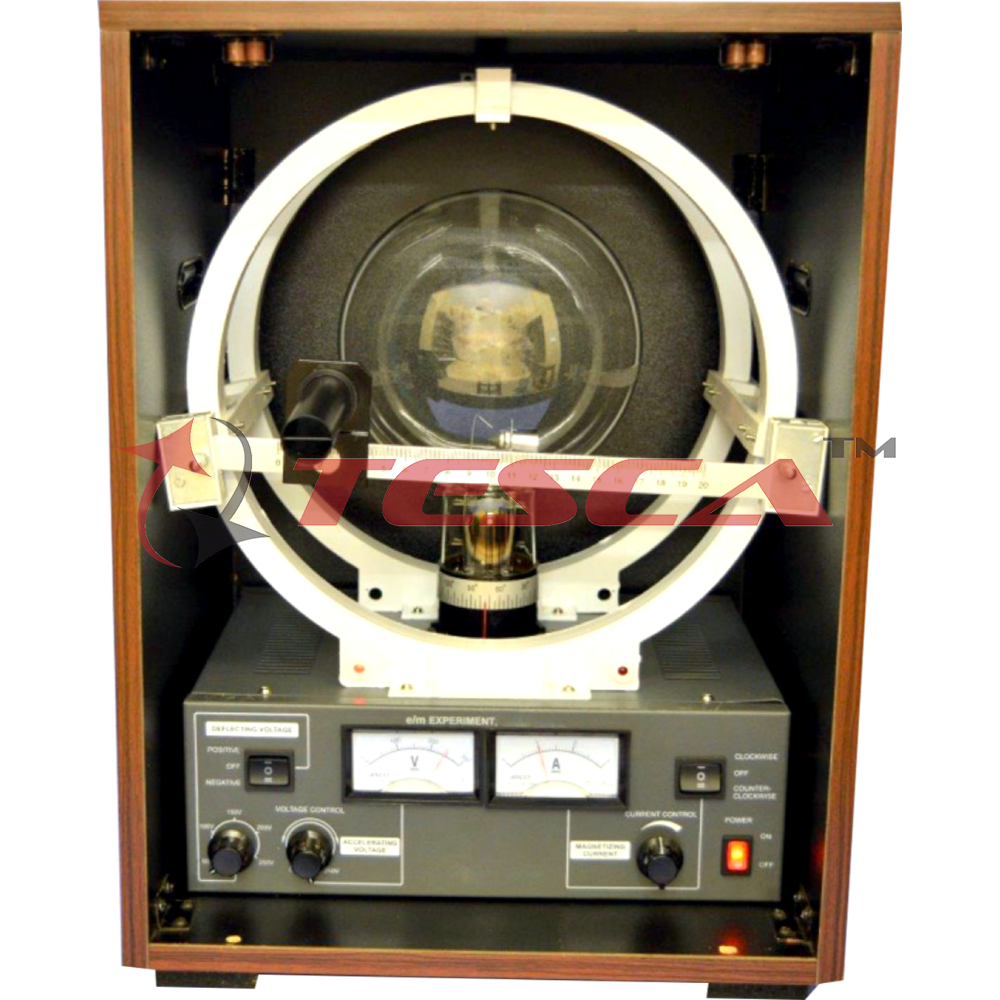
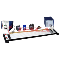
E/M Experiment based on Thompson Method
Order Code: 55521
Category: Physics Trainers
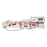
The Vibrating Sample Magnetometer (VSM) measures the magnetization of a sample of magnetic material under an external magnetic field by converting the dipole field of the sample into an ac electrical signal. A vibrator along with its electronics vibr...
SPECIFICATION
Description of the experimental set-up
Enquiry Form
Related Product


Tesca specialize in doing turnkey projects that is fully operable when it is handed over to the project authority. Starting from inception to application training, Tesca provides the services as ONE source solution. Working side by side with government authorities and people across the World, we help countries to perform better. We support countries grow their economies, strengthen their education and health systems and improve financial management. We do this by providing consultancy & training in environment safety, education, health strengthening.
Category
Useful Links
Contact Us
International Sales:
 91-9829132777
91-9413330765
India Sales:
91-9588842361
2026 © All Rights Reserved.