
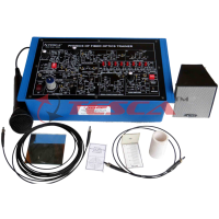
Erbium Doped Fiber Amplifier Module
Order Code: 28561
Category: Fiber Optic Trainers
Features EDFA System enables student to experimentally investigate the principles and characteristics of EDFA in C Band ( 1530nm – 1565 nm) Demonstrates amplification of 1550 nm wavelength along with the detection and measurement of amp...
SPECIFICATION
Features
- EDFA System enables student to experimentally investigate the principles and characteristics of EDFA in C Band ( 1530nm – 1565 nm)
- Demonstrates amplification of 1550 nm wavelength along with the detection and measurement of amplified signal.
- Investigation and Analysis of Small and Large Signal Gain
- Facility to implement Forward and Backward Pumping and Study Gain Characteristics
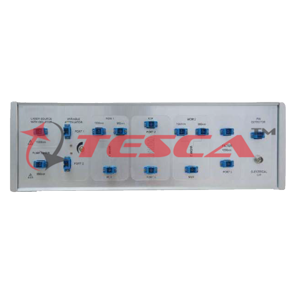
Edfa block diagram
- 1550nm signal and 980nm pumped inside EDF
- 2:1 WDM system is used to combine pump and optical signal (1550nm)
- The Erbium atoms absorb 980nm pump signal and jump to higher energy state
- 1550nm strikes excited Er+3 ions and initiate Stimulated Emission
- 1550nm amplified by stimulated emission
Amplification principle
- Figure above describe the energy level diagram for Er+3 ion
- 1480 nm pump excites Er+3 to quasi metastable stage
- Coincidently, emits wavelengths in the range 1525- 1565nm range while returning back to ground state fromquasi-metastable stage
- This amplifies the signal by stimulated emission.
Specifications
Lasers @1550nm
- 1.25 Gbps Laser Diode Module at wavelength of 1550nm
- In Built Isolator
- Channel Spacing : 20 nm
- Threshold Current Ith : 10 mA Typical
- Output Power : @ Ith + 30 mA - > 0.7 mW @ ~ 58 mA-> 1.4 mW
- Operating Voltage : 1.1V Typical
PUMP LASER@980nm
- Up to 100 / 150mW Uncooled 980nm Pump Module
- Maximum Operating Power : 100 / 150mW
- Maximum Operating Current : 340mA
- Center Wavelength : Min 970nm Max 980nm
- Optical Connector : SC/PC
Optical Detector
- 1.5 GHz InGaAs PIN Photodiode Module.
- Responsivity : Typical 0.9 A/Win 9/125 μmfiber
- Spectral Range : 1250nm to 1600nm
- Reverse Voltage : 30 V max.
- Optical Connector : SC/PC
Wavelength Division Multiplexer
- Operating Wavelength(nm) : 980/1550
- Max. Insertion Loss (dB) : 0.20
- Isolation (dB) : >20
- Polarization Sensitivity(dB) : <0.05
Erbium doped fiber
- The core of the fiber is doped with Erbium.
- In EDF fiber core acts as gain medium or Host
- MFD (Nominal) : 5.5 - 6.3um@1550nm
- Core NA : 0.21 - 0.24
- Cut - off Wavelength : 900 - 940nm
- C-Band Single Mode Fiber (1530 - 1565nm)
- Peak Absorption : 4.5-5.5 dB/m@980nm; : 5.4-7.1 dB/m@1531nm
Optical filter
- An optical filter is a device that selectively transmits light of different wavelengths, usually implemented as a glass plane or plastic device in the optical path, which are either dyed in the bulk or have interference coatings.
- Center Wavelength : 1550nm@ 2nm BW
- Pass bandwidth @0.5dB : 2.0nm
- Return Loss : ≥ 50dB
Variable attenuator
- An optical attenuator, or fiber optic attenuator, is a device used to reduce the power level of an optical signal
- The power reduction is done by such means as absorption, reflection, diffusion, scattering, deflection, diffraction, and dispersion, etc. optical attenuators usually work by absorbing the light.
- Attenuation Range : 0.8 to 60dB
- Wavelength : 1550nm
Software
- User friendly GUI for monitoring, controlling of EDFA system
- Operating modes like CW mode, VI characteristics mode, Internal & External Modulation
- LASER control like Supply ON/OFF, wavelength selection and driving current selection.
- Real time signal level monitoring of Photo-detector.
- Graphical representation : XY plot of VI characteristics and Internal Modulation
- COM Settings : USB 2.0
Software interface
1. Vi characterisation of pump and lasersource
- Above picture shows the VI characteristics of pump and source LASER.
- VI characteristics of both LASERs could be observed in the software by selecting VI characteristics in the Operating Mode option.
2. Laser controls
- Individual LASER voltage can be controlled using slider provided in software
- LASER voltage and corresponding LASER current is displayed on the screen
3. Modulation mode
- LASER voltage controls provided
- Select LASER on Left column
- Internal and External modulation options available
- 4 Modulation frequencies(100Hz, 200Hz,500Hz,1KHz) can be used
- Modulated signals displayed on graph in right column
4. Optical spectrum analyzer display
- Output Spectrum of EDF with Signal Source (1550nm)
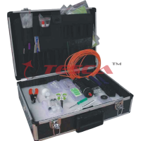
Accessories
- Shielded USB A-A cable : 01No
- Power Cable : 01No
- SC-SC Single Mode Fiber : 06No
- Optic Patch Chords
- BNC to BNC coaxial cable : 01No
- Software on CD : 01No
- FTDI Drivers
- Experimental Manual : 01No
Enquiry Form
Related Product


Tesca specialize in doing turnkey projects that is fully operable when it is handed over to the project authority. Starting from inception to application training, Tesca provides the services as ONE source solution. Working side by side with government authorities and people across the World, we help countries to perform better. We support countries grow their economies, strengthen their education and health systems and improve financial management. We do this by providing consultancy & training in environment safety, education, health strengthening.
Category
Useful Links
Contact Us
International Sales:
 91-9829132777
91-9413330765
India Sales:
91-9588842361
2026 © All Rights Reserved.