
Ferroelectric PE Loop Tracer
Order Code: 55549
Category: Physics Trainers
Research in the area of ferroelectrics is driven by the market potential of next generation memories and transducers. Thin films of ferroelectrics and dielectrics are rapidly emerging in the field of MEMS applications. Ultrasonic micro-motors utilizi...
SPECIFICATION
Research in the area of ferroelectrics is driven by the market potential of next generation memories and transducers. Thin films of ferroelectrics and dielectrics are rapidly emerging in the field of MEMS applications. Ultrasonic micro-motors utilizing PZT thin films and pyroelectric sensors using micromachined structures have been fabricated. MEMS are finding growing application in accelerometers for air bag deployment in cars, micro-motors and pumps, micro heart valves, which have reached the commercial level of exploitation in compact medical, automotive, and space applications. Extremely sensitive sensors and actuators based on thin film and bulk will revolutionize every walk of our life with Hi-Tech gadgets based on ferroelectrics. Wide spread use of such sensors and actuators have made Hubble telescope a great success story. New bulk ferroelectric and their composites are the key components for the defence of our air space, the long coastline and deep oceans.
Measurement Technique
The commonly accepted criterion of ferro-electricity is a hysteresis loop. This is usually done with the help of a cathode ray oscilloscope. In this method, an alternating high voltage is applied and the stored charge is related to the instantaneous voltage. A large integrating capacitor (standard capacitor) is placed in series with the sample. The voltage across it measures the charge stored on the test sample and is conventionally displayed as the vertical deflection of the cathode ray oscilloscope. The applied voltage is displayed as the horizontal deflection. Block diagram of our system is given in Fig 2. It has a provision to compensate conductive unwanted signals so as to get pure ferroelectric loop.
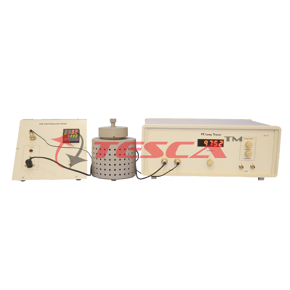
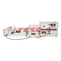
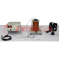
Description of Experimental Set-up
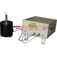
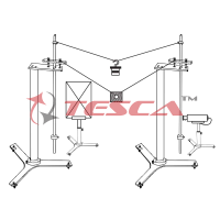
1. Probes Arrangement
In this arrangement one probe is held fixed and the other is spring loaded for placing the sample as well as making the proper connection. All care has been taken to avoid voltage hazards and yet convenient to replace the sample.
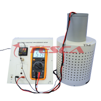
Provision has also been made for dipping the contacts in high voltage oil to avoid discharge due to high voltage. It also includes a furnace for determining Curie Temperature.
2. Sample
Barium Titanate (BaTiO3) pellet
3. Main Unit
(i) High Voltage Oscillator
Amplitude:0-10,000 Vpp
Frequency:~100Hz
Waveform:Low distortion sine wave
(ii) Signal Processing Circuit
It contains front end amplifier, conductive and capacitive compensation circuit and finally appropriate signal conditioning to display on CRO.
Application
- Following measurements can be done by this setup
- Study the beaviour of maximum polarisation (Pm)
- Study the remnant polarization (Pr)
- Study the coercivity with electric field (Ec)
- Curie Temperature (Tc)
- Behaviour of Ec, Pr, Pm vs Temperature at Constant Electric Field
Computer Connectivity
PE Loop Tracer Setup can be connected to a computer for acquiring data for data logging purposes. The data can be stored in excel file which can be used for further analysis. Software is menu driven and very easy to operate. All loops are visible on Computer Screen ain real time.
Necessary hardware - TESCA CAMM and its software is provided along with the setup.
The setup is complete in itself, except a Computer or Oscilloscope
Enquiry Form
Related Product

Tesca specialize in doing turnkey projects that is fully operable when it is handed over to the project authority. Starting from inception to application training, Tesca provides the services as ONE source solution. Working side by side with government authorities and people across the World, we help countries to perform better. We support countries grow their economies, strengthen their education and health systems and improve financial management. We do this by providing consultancy & training in environment safety, education, health strengthening.
Category
Useful Links
Contact Us
International Sales:
 91-9829132777
91-9413330765
India Sales:
91-9588842361
2026 © All Rights Reserved.