
Flow Measurement
Order Code: 22235750.30
Category: General Lab Equipment II
Key Features Includes Venturi meter, orifice plate and rotameter Works with Digital Hydraulic Bench for easy installation Direct measurement of head loss Three different flow meters that work with Bernoulli’s equation Multi-tube m...
SPECIFICATION
Key Features
- Includes Venturi meter, orifice plate and rotameter
- Works with Digital Hydraulic Bench for easy installation
- Direct measurement of head loss
- Three different flow meters that work with Bernoulli’s equation
- Multi-tube manometer shows pressure at various points
- Works with optional, free Hydraulics Data Management System Software (HDMS)
Key Specifications
- Venturi meter, orifice plate and rotameter
- Sudden enlargement and 90° elbow
- Eleven manometer tubes
- Down stream flow control valve
Learning Outcomes
Study of Bernoulli’s equation, flow measurement and losses, including:
- Application of the Bernoulli equation for incompressible fluids
- Direct comparison of flow measurement using a Venturi meter, orifice plate and rotameter
- Comparison of pressure drops across each flow measurement device
- Comparison of pressure drops across a sudden enlargement and a 90-degree elbow
Description
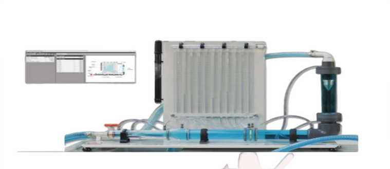
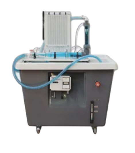
The Flow Measurement apparatus shows the typical methods of measuring the flow of an essentially incompressible fluid (water). It also shows applications of Bernoulli’s equation. Students measure flow using a Venturi meter, an orifice plate meter and a rotameter. Students find and compare the head losses associated with each meter, as well as those arising in a rapid enlargement and a 90-degree elbow. The apparatus is for use with Hydraulic Bench (available separately). The product has a horizontal pipe that includes a Venturi meter, orifice plate and pressure tappings. An elbow connects the pipe to a rotameter(gap-type flow meter) with further pressure tappings.
All pressure tappings connect to manometers held on a vertical panel behind the pipe work. The manometers measure and show pressure distribution against a calibrated scale.
To perform experiments, students connect the product to the hydraulic bench supply, and set it to a low, steady flow through the apparatus. Water from the hydraulic bench then flows through the Venturi meter, through a sudden enlargement, a settling length and the orifice plate. It then flows around theelbow, through the rotameter, then a flow control valve, finally returning to the hydraulic bench. The control valve is downstream, so it does not cause any upstream turbulence.To adjust the datum water level in the manometer tubes, students connect a hand-pump (included) to the valve above the manometer tubes. Students measure the flow using the hydraulic bench, noting the manometer levels and rotameter reading. They then increase the flow in set increments, taking readings each time, until reaching maximum flow rate. They then use Bernoulli’s equation to find mass flow rate through each of the meters, comparing to flow rates measured using the hydraulic bench. Students can compare advantages, disadvantages and potential applications of each meter. If required students can download Hydraulics Data Management System (HDMS) software onto a suitable computer (not supplied) to aid with entering, evaluating and presenting their data.
Standard Features
- Supplied with a comprehensive user guide
- Five-year warranty
- Manufactured in accordance with the latest European Union directives
- ISO9001 certified manufacturer Essential Base Unit
Essential Base Unit
- Digital Hydraulic Bench :-This product will also work with existing Gravimetric and Volumetric Hydraulic Benches
Typical Work Assignment
Calibration of the Rotameter
The results from tests at different flow rates can produce a chart that compares the height ofthe float in the rotameter with the flow rate measured by the hydraulic bench, producing a calibration chart for the rotameter. The chart should show an almost linear response when compared to flow in litres per minute.
Hydraulics Data Management System
The HDMS is a complimentary software tool designed to help students accurately record data from experiments associated with this apparatus. The software is intuitive and easy to use, with clear and convenient data display options, enabling students to run automatic calculations and export charts and results for further investigation.
Detailed Specifications
Is committed to a programme of continuous improvement; hence we reserve the right to alter the design and product. specification without prior notice.
Nett dimensions and weight:
900 mm x 380 mm x 900 mm and 10 kg
Approximate packed dimensions and weight:
0.31 m3 and 19 kg
Orifice plate:
20 mm diameter with corner tappings
Sudden enlargement:
26 mm to 51.9 mm
Rotameter:
Scaled 0 to 210 mm. Includes calibration chart for 0 to 35 litres per minute.
Manometer:
Scaled 0 to 380 mm
Maximum flow:
28 litres per minute
Accessories (included):
All necessary tubing and pipe clips Operating Conditions
Operating environment:
Laboratory
Storage temperature range:
–25oC to +55oC (when packed for transport)
Operating temperature range:
+5oC to +40oC
Operating relative humidity range:
80% at temperatures < 31oC decreasing linearly to 50% at 40oC
Enquiry Form
Related Product


Tesca specialize in doing turnkey projects that is fully operable when it is handed over to the project authority. Starting from inception to application training, Tesca provides the services as ONE source solution. Working side by side with government authorities and people across the World, we help countries to perform better. We support countries grow their economies, strengthen their education and health systems and improve financial management. We do this by providing consultancy & training in environment safety, education, health strengthening.
Category
Useful Links
Contact Us
International Sales:
 91-9829132777
91-9413330765
India Sales:
91-9588842361
2026 © All Rights Reserved.