
FPGA CPLD Traine
Order Code: 25269143.3
Category: General Lab Equipment V
Key Features Advanced FPGA Development training Board designed based on the latest digital techno! ogy in conjunction with EDA expel imental teaching material. This training system consists of FPGA chip with higher logic elements and large number of...
SPECIFICATION
Key Features
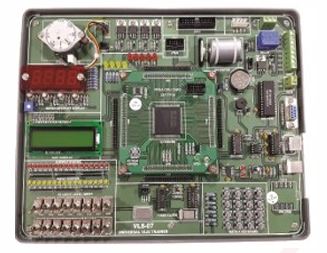
Advanced FPGA Development training Board designed based on the latest digital techno! ogy in conjunction with EDA expel imental teaching material. This training system consists of FPGA chip with higher logic elements and large number of pins. Therefore, students are able to develop, implement and verify design of basic or advanced digital circuit, digital signal processor and CPU/MCU. This system is equipped with ADC/DAC analog module, keyboard, LCD Jisplay, PS2, VAA, UART. SCI interface, LEDs, 8-digit \’- segment displays, DC motor and stepper motor which allow students to handle complex mixed signal design and digital control design.
Advance FPGA Development System is well equipped for complex digital circuit design. lt provides AD/DA converter keypad, LCD display, PS/2, VGA, UART, SCI interface, LEDS, 8 digit 7-segment LED display, step motor and DC motor driver circuits.Suitable for the curriculum training in electronics, electrical engineering, information, communication and automation field.Ideal for professional IC designers, R&G engineers, undergraduate and gracduate students to learn IC design and software development. Develop and verify basic and advanaed Digital circuit, digital signal processing and CPU / MCU with large-e!ement and multi-pin FPGA chip.
Specification :
Download Board
- Chip mudel : Altera cyclone EP1C12Q240C8
- Clock : 40MHz
- Configuration interface : USB blaster
- Configuration memory . 2MB flash SEEPROM
Peripheral i/Os
1.) Power unit
- 3V/3A,
- 5V/3A
2.) Input and clocking unit :
- 4 sets of 8-bit DIP Switch
- 4x4 matrix keypad
- Rotary encoder switch (A/B phase)
- Intrared coupled receiver
- 10 sets of fixed selectable clock : 0.1Hz, 1Hz, 10Hz, 109Hz, 1KHz, 10KHz., ’. 00KHz, 1MHz, 10MHz, 40MHz
- 1 toggle Switch
- 4 configurable push-button . Positive/negative pulse output and debounced / non debounced pulse output.
3.) Output unit
- 8 sets of 8-bit buffered LED (red / orange / yellow / green)
- 4 independent LED (red)
- 2 groups of 4-digit 7-segment scaning display
- 128x64 graphic / character LCD display
- 8x8 dot matrix LED display (dual color)
- 16-segment display
- Speaker (8ohm/0.5W)
- Infrared coupled transmitter
4.)Interface unit .
- PS2 interface
- VGA interface (8 x 8 x 8 bit color) a
- RS-232 interface
5.) Motor unit :
- Step motor : 12V/250mA, 7.5 degree/ step
- 4 poles step motor driving circuit : Each pole drives 60V/500mA
- 4 stage PWM-bridged control circuit : Each stage drives 50V/3A with forward / reverse and
6.) Chip Comunication and expansion unit
- 8-bit D/A converter (memory mapping interface)
- 6-bit A/C converter (memory mapping interface)
- 23SK bits SEEPROM (llC interface)
- 12-bit dual channel serial D/A converter (SPI interface)
- Micro-controller 89C51 (memory mapping interface)
- 40-pin external connector x 1
- 20-pin external connector x 2
Experiments
Basic logic circuit design and application
- QUARTUS II software installation and operation
- Basic combinational logic circuit
- Basic sequential logic circuit
- Basic arithmetic logic Circuit
- Using mega function
- Numerical code conversion circuit
Advanced logic circuit design and application
- 48-bit up/down counter with load, clear anò enable
- Infrared coupled transce.vorr controls 8-digit decimal scanning counter
- Rotary encoder switch detector
- 16-segment LEDs digital display decoder
- 8 x 8 x 2 color dots matrix graphic display control
- 4 x 4 scanning matrix keypad control
- 128 x 64 LCD module display control
- ADC conversion with hexadecimal and decimal display
- DAC conversion for precise frequency generator
- Precise function generator controlled by keypad
- 8 x 8 x 8 color pixels uf VGA display control
- Interfacing with synchronous serial PS/2 keyboard
- Step motor position controlled by keypad
- Step motor speed controlled by keypad
- Using QUARTUS built in real time logic analyzer
- High speed frequency and period counter
- Digital clock
- Music box
- Electronic piano
- Digital cipher locker
- Digital cipher locker with hopping code
- Bingo machine
- Electronic dices
- Traffic light control
- Serial DAC Transmission
- IIC transmission
- UART transmission
- Interfacing with MCU
- Building NIOS CPU from SOPC developmental system
Enquiry Form
Related Product

Tesca specialize in doing turnkey projects that is fully operable when it is handed over to the project authority. Starting from inception to application training, Tesca provides the services as ONE source solution. Working side by side with government authorities and people across the World, we help countries to perform better. We support countries grow their economies, strengthen their education and health systems and improve financial management. We do this by providing consultancy & training in environment safety, education, health strengthening.
Category
Useful Links
Contact Us
International Sales:
 91-9829132777
91-9413330765
India Sales:
91-9588842361
2026 © All Rights Reserved.