
Friction loss in pipes App

Order Code: 21224953.2.50
Category: General Lab Equipment II
List of Experiments : 1. Familiarization and training with pressure and fluid flow measurements. 2. Study of pipe friction at various flow velocities. 3. Study of pipe friction in laminar and turbulent flows. 4. Study of effect of surface rough
SPECIFICATION
Specifications:-
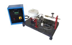
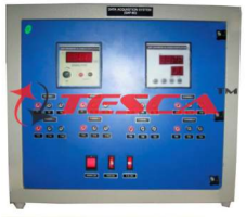
Study of friction loss in pipes is important in view pumping power requirements. The Friction Loss in Pipes Apparatus is an important experimental set-up for any Fluid Mechanics and Hydraulics Laboratory of an educational institution. The apparatus has been designed to enable student measure loss of head in pipes due to friction at various flow velocities or Reynolds numbers. The geometry and flow parameters have been selected to enable studies in the ranges of practical interest.Friction Loss in Pipes Apparatus is mounted on a supporting rigid structure mounted on wheels/stand and is designed for use with the Hydraulic Bench or any other suitable controlled water supply and recirculation system. The flow velocity is measured using the calibrated variable area flow meter and the measuring tank of the Hydraulic Bench. The head loss due to friction is measured using a suitably placed static pressure tapings, multi-tube manometer and digital pressure meter. Flow velocity or Reynolds number can be varied. A system of parallel pipe net work configuration and isolating valves enable tests to be conducted on different pipes without disconnecting or draining the system.
Important Features and Specifications:
The Apparatus includes the following pipes for testing:
-
Smooth bore pipes: 27, 14 and 3.5 mm bore, 1800mm length, PVC.
-
Artificially roughened pipes, 23 and 17 mm bore, 1800mm length, PVC.
Color coding for piping system will be selected to suit user requirements.
Pressure tapping is by small ball valves with quick connections will be provided at inlet and exit. Pressures are measured using multi-tube manometer. Pressure taps are connected to a set of manifolds by flexible pressure hoses such that differential pressure across pipe length can be measured by opening valves without removing the hoses.
Flow measurement using Variable Area Flow Meter and measurement tank of the Hydraulic Bench.
Water Manometer with hand air pump, 8 tubes X 800 mm with 1mm reading
Mercury Manometer, 2 tubes X 500 mm with 1mm reading.
Digital Pressure Meter.
Options:
1. Based on the request by the user, it is possible to include any other types of pipe (material and bore) in the apparatus.
-
90 ° Bend
-
90 ° Elbow
-
90 ° Tee
-
45 ° Elbow
-
Sudden Enlargement
-
Sudden Contraction
-
Inline Strainer
-
Friction in Pipes Apparatus with computer control and data acquisition and electronic transducers for flow and pressure measurements can be provided on request.
-
A Floor Mounted unit of the Friction in Pipes Apparatus mounted on a mobile platform and with a flow controlled closed circuit water circulation unit consisting of centrifugal pump, flow meter, corrosion resistant sheet metal flow measuring tank and a sump tank can be supplied on request.
-
Interactive Computer Aided Instruction Software System
-
Computer Control Software
-
PID Computer Control + Data Acquisition + Data Management Software for Linear Heat
-
Conduction Module.
-
Compatible with actual Windows operating systems. Graphic and intuitive simulation of the processin screen. Compatible with the industry standards.
-
Registration and visualization of all process variables in an automatic and simultaneous way.
-
Flexible, open and multi-control software, developed with actual windows graphic systems, acting simultaneously on all process parameters.
-
Analog and digital PID control.
-
Menu for PID and set point selection required in the whole work range.
-
Management, processing, comparison and storage of data.
-
Sampling velocity up to 250 KS/s (Kilo samples per second).
-
Calibration system for the sensors involved in the process.
-
It allows the registration of the alarms state and the graphic representation in real time.
-
Comparative analysis of the obtained data, after the process and modification of the conditions during the process.
Enquiry Form
Related Product


Tesca specialize in doing turnkey projects that is fully operable when it is handed over to the project authority. Starting from inception to application training, Tesca provides the services as ONE source solution. Working side by side with government authorities and people across the World, we help countries to perform better. We support countries grow their economies, strengthen their education and health systems and improve financial management. We do this by providing consultancy & training in environment safety, education, health strengthening.
Category
Useful Links
Contact Us
International Sales:
 91-9829132777
91-9413330765
India Sales:
91-9588842361
2026 © All Rights Reserved.