
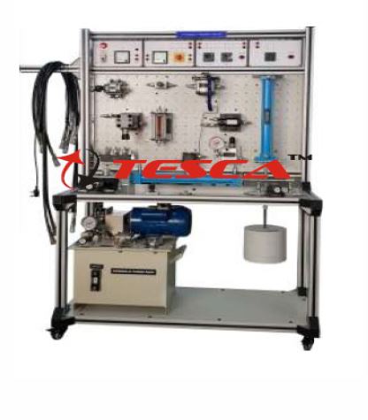
Hydraulic Training System
Order Code: 23246831.3
Category: General Lab Equipment III
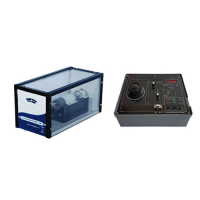
Technical Parameter Hydraulic operation station:It consists of aluminum material profile, Experiment table dimension (minimum):1600 (length) ×750 (width) x1780 (height) mm Aluminum panel dimension(minimum):1200 (length) x600 (width) ...
SPECIFICATION
Technical Parameter
- Hydraulic operation station:It consists of aluminum material profile,
- Experiment table dimension (minimum):1600 (length) ×750 (width) x1780 (height) mm
- Aluminum panel dimension(minimum):1200 (length) x600 (width)
- Groove gap:25mm
- Aluminum wood cabinet: 1 piece
- Caster with crack groove: 4 pieces
- Groove plate insert and extract system
- Hydraulic components
- Hydraulic pump station
- Work power: AC: 380~400V
- Frequency: 50Hz
- Safety speed limit range: 1000-1500 r/min
- Power: 1.5KW (Minimum)
- Flow :6L/min (Minimum)
- Electrical control module:
- Power module: with three phrase leakage protection, output voltage:380V
- Dc power module: output voltage DC-24V
- Rated current: 5A
- Button module: signal light power: DC24V Contact capacity AC-220V/1A DC-24V/2A Machine electric life span: one million times
- Relay module: coil voltage: DC24V;
- Contact capacity: AC-240V/10A/ DC-24V/10A
- Mechanism life: one million times
- Proportion shuttle valve amplifier Power: DC-24V
- Control voltage:+9V±2%
- Max output current:1800Ma
- Ramps time: 0.02s-5s
- Proportion relieve valve amplifier:
- Power: DC-24V
- Rated current:800mA
- Control range: DC0~+5V or DC0~+10V
Experiment contents:
Basic electric control
a) Lights on control
b) Lights out control
c) And logic control
d) Or logic control
e) Logic combination control
f) Relay self-lock control
g) The usage of proximity sensor
Hydraulic control circuit
1.Direction control circuit
- manual shuttle valve reversing circuit
- solenoid valve reversing circuit
- lock circuit
2.Pressure control circuit
- Single grade pressure regulating circuit
- Secondary level pressure regulating
- Single pressure reducing circuit
- Level 2 pressure circuit
- The unloading circuit using ''''M'''' ''''H'''' type manual shuttle valves
- The unloading circuit using pilot relief valve
- The balance circuit using the sequence valve
- Liquid control one-way valve pressure maintenance.
- The one-way back pressure circuit using relief valve
3.The flow speed regulator circuit using throttle valve
- Enter oil-way throttle speed regulation
- Back oil-way throttle speed regulation
- Side oil-way throttle speed regulation
4.The speed regulator circuit using speed regulator valve
- Enter oil-way throttle speed regulation
- Back oil-way throttle speed regulation
- Side oil-way throttle speed regulation
- Speed synchronous circuit of the speed regulation valve
- The parallel circuit of speed regulation valve
5.Fast moving circuit of hydraulic cylinder differential connection
6.Fast moving circuit of hydraulic cylinder differential connection
7.Sequence action circuit using sequence valve
8.Sequence action circuit use stroke switch control
9.Sequence action circuit use pressure relay control
10.One-way atresia circuit use hydraulic control one-way valve
11.Double-way atresia circuit use hydraulic control one-way valve
12. The lock circuit using O type shuttle valve
13. Relay control hydraulic basic circuit
Proportion hydraulic circuit experiment
- Proportion amplifier principle
- Proportion amplifier application
- Magnetic proportion shuttle valve application
- Hydraulic motor speed control
- Hydraulic motor reversal control
Accessories:
- Hydraulic oil Compressor-01 no
- Connecting jack 2mm & 4mm : 01 Set
- Power Cable: 01 no
- PLC to PC Communication cable: 09 Sets
- Simulation software for compatible PLC
- English Manual & CD: 01 Set.
- Installation, Commissioning and provide necessary operational training by Bidder.
- Warrenty: 1 (One) Year.''
Enquiry Form
Related Product


Tesca specialize in doing turnkey projects that is fully operable when it is handed over to the project authority. Starting from inception to application training, Tesca provides the services as ONE source solution. Working side by side with government authorities and people across the World, we help countries to perform better. We support countries grow their economies, strengthen their education and health systems and improve financial management. We do this by providing consultancy & training in environment safety, education, health strengthening.
Category
Useful Links
Contact Us
International Sales:
 91-9829132777
91-9413330765
India Sales:
91-9588842361
2026 © All Rights Reserved.