
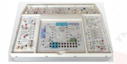
Industrial Electronics Trainer Part-03
Order Code: 23246836.10
Category: General Lab Equipment III
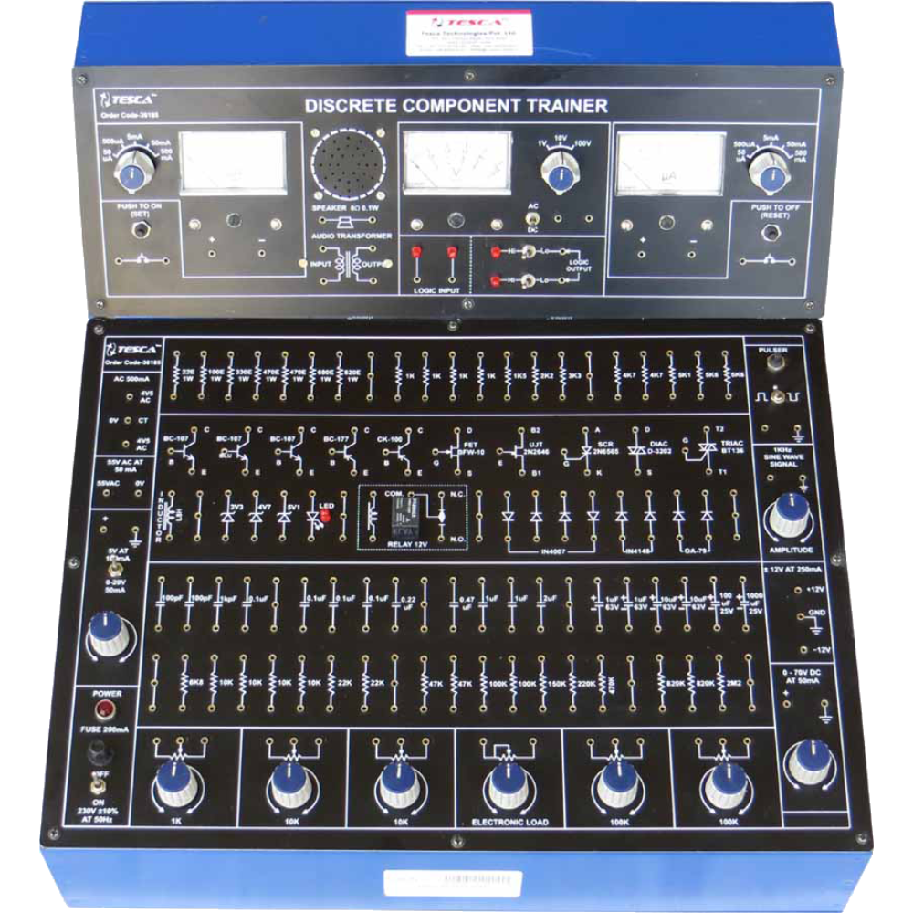
Experimental Training Board has been designed specifically for the study of Discrete Electronic Components. It contains a wide selection of discrete components and A.C. & D.C. Power Supplies. The capabilities of this trainer extend far beyond the...
SPECIFICATION
Experimental Training Board has been designed specifically for the study of Discrete Electronic Components. It contains a wide selection of discrete components and A.C. & D.C. Power Supplies. The capabilities of this trainer extend far beyond the experiments described. Although only a finite number of experiments have been described yet other circuits as per individuals requirements can also be designed using the available components and power supplies.
Practical experience on this board carries great educative value for Science and Engineering Students.
Object
RC & LC CIRCUITS :
- Study of RC High Pass Filter
- Study of RC Low Pass Filter
- Study of RL Differentiating Circuits
- Study of Series RC Circuit
- Study of Series LC Circuit
- Study of Parallel RC Circuit
- Study of Parallel LC Circuit
SERIES & PARALLEL RESONANCE CIRCUIT :
- Study of Series LCR Resonance Circuit and determination of ‘Q’
- Study of Parallel LCR Resonance Circuit
- Determination of impedance & reactance of reactive elements and plotting of reactive curves
GERMANIUM & SILICON DIODES :
- Characteristics of a germanium diode
- Characteristics of a silicon diode
- Application of a diode as a half wave rectifier
- Application of four diodes as full wave bridge rectifier
ZENER DIODE :
- Characteristics of a Zener Diode
- Application of a Zener Diode as a voltage regulator
- Determination of line regulation of a zener diode regulator circuit
- Determination of load regulation of a zener diode regulator circuit
CLIPPING & CLAMPING CIRCUITS :
- Study of single level clipping circuits
- Study of two level clipping circuits
- Study of clamping circuits
COMMON EMITTER CONFIGURATION OFATRANSISTOR :
- Input characteristics of common emitter configuration
- Output characteristics of common emitter configuration
- Study of common emitter amplifier
COMMON BASE CONFIGURATION OF ATRANSISTOR:
- Input characteristics of common base configuration
- Output characteristics of common base configuration
- Study of common base amplifier
COMMON COLLECTOR CONFIGURATION OFATRANSISTOR :
- Transfer characteristics of common collector configuration
EMITTER FOLLOWER ( TRANSISTOR) :
- Study of emitter follower configuration
CASCADED AMPLIFIER :
- Study of two stage cascaded amplifier
POWER AMPLIFIER
- Study of class-A power amplifier
DIFFERENTIALAMPLIFIER :
- Study of a differential amplifier and determination of its CMRR
FEED BACK AMPLIFIER
- Study of current series feedback
- Study of current shunt feedback
SELECTIVE AMPLIFIER :
- Study of frequency selective amplifier
FET CHARACTERISTICS & SOURCE FOLLOWER:
- Study of static characteristics of an FET
- Application as source follower
FET CHOPPER & V.V.R. (Voltage Variable Resistor)
- Application as a Chopper
- Application as Voltage Variable Resistor (VVR)
R.C. PHASE SHIFT OSCILLATOR :
- Study of R.C. Phase Shift Oscillator
U.J.T. CHARACTERISTICS & RELAXATION OSCILLATOR :
- Study of UJT Characteristics
- Application of UJT as relaxation oscillator
TRIAC CHARACTERISTICS :
- Terminal Characteristics in Mode I+
- Terminal Characteristics in Mode III+
- Measurement of Holding Current IH
- Gate characteristics in Mode I+
- Gate characteristics in Mode I-
- Gate characteristics in Mode III+
- Gate characteristics in Mode III-
- Application in power control using D.C. control voltage
- Application in power control using A.C. control voltage
BISTABLE MULTIVIBRATOR :
- Study of bistable multivibrator circuit
MONOSTABLE MULTIVIBRATOR :
- Study of monostable multivibrator circuit
ASTABLE MULTIVIBRATOR :
- Study of astable multivibrator circuit
SCHMITTTRIGGER :
- Study of Schmitt Trigger circuit
ASIC LOGIC GATES :
- Study of AND gate
- Study of OR gate
- Study of NAND gate
- Study of NOR gate
LED CHARACTERISTICS & APPLICATIONS :
- Study of Characteristics of LED
- Application of LED in constant current sources
SCR CHARACTERISTICS :
- D.C. gate control characteristics
- Anode current characteristics
DIAC CHARACTERISTICS & APPLICATIONS :
- Study of Characteristics of a Diac
- Application as sawtooth wave & pulse generator
- Application in Diac Triac Power control circuit
Features:
The board consists of the following built in parts :
- 4V5-0-4V5 A.C. at 500 mA, Power Supply.
- 0-5VA.C. at 50mA, Power Supply.
- 0-70V D.C. at 50 mA, continuously variable Power Supply.
- ± 12V D.C. at 250 mA, IC regulated and short circuit protected Power Supply.
- 0-20V D.C. at 50 mA, IC Regulated Power Supply.
- 5V D.C. at 100mA, IC Regulated Power Supply.
- A.C. / D.C. Voltmeter, 65mm rectangular dial, with switch selectable ranges of 1V, 10V and 100V.
- Two D.C. Ammeters, 65mm rectangular dial, with switch selectable ranges of 50 mA/500mA/5mA/50mA/500mA.
- Pulser with Dual Polarity, selectable output.
- 1 KHz Sine wave source with variable output level.
- LEDs for visual indication of Input & Output status.
- Speaker, LED, 8 diodes, 5 Zener diodes, Diac, SCR, Triac, 2 FET, UJT, 7 Transistors, 1 matched transistor pair, 67 resistors, 27 capacitors, 6 potentiometers, Electronic Load, indicator, Audio Transformer.
- 12 V, OEN Relay with one change over contacts rated at 6 Amp. for resistive and 3 Amp. for inductive Load at 230V.
- Mains ON/OFF switch, fuse and Neon Indicator are provided.
The unit is operative on 230V ±10% at 50Hz A.C. Mains.
Adequate no. of patch cords stackable from rear both ends 2mm spring loaded plug length ½ metre.
Good Quality, reliable terminal/sockets are provided at appropriate places on panel for connections & observation of waveforms.
Strongly supported by detailed Operating Instructions, giving details of Object, Theory, Design procedures, Report Suggestions and Book References.
Other Apparatus Required:
- Sine Square Wave Oscillator
- Cathode Ray Oscilloscope 20MHz
Enquiry Form
Related Product


Tesca specialize in doing turnkey projects that is fully operable when it is handed over to the project authority. Starting from inception to application training, Tesca provides the services as ONE source solution. Working side by side with government authorities and people across the World, we help countries to perform better. We support countries grow their economies, strengthen their education and health systems and improve financial management. We do this by providing consultancy & training in environment safety, education, health strengthening.
Category
Useful Links
Contact Us
International Sales:
 91-9829132777
91-9413330765
India Sales:
91-9588842361
2026 © All Rights Reserved.