
Industrial Power system Trainer
SPECIFICATION
Industrial Power system Trainer
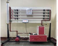
System Overview
- This trainer is a dual-panel industrial simulation system designed to bridge theoretical power systems knowledge with practical installation and troubleshooting skills.
- It simulates a complete power cycle: Grid/Generator Input -> Automatic Transfer -> Multi-stage Distribution -> Industrial/Domestic Load Control.
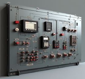
Panel A: Main Distribution Board (MDB)
- The MDB serves as the primary protection, metering, and distribution hub.
- Core Specifications:
- Incomer: 63A 3P MCCB equipped with a Motorized Actuator and Under Voltage Trip (UVT) coil for automated safety logic.
- Leakage Protection: Earth Leakage Relay (ELR) integrated with a Core Balance Current Transformer (CBCT) for high-sensitivity fault detection.
- Distribution: RCCBs: 40A 30mA 2P (×3) for residual current protection. MCBs: 6A, 10A, and 16A (×3 each) for branch circuit overcurrent protection.
- Metering & Analysis: Digital Power Analyzer supported by three 60:5A CTs and a Power Factor Relay (PFR) with an 11-pin base.
- Bus Bar System: 100A copper bus bars with insulators and a transparent acrylic safety cover for visual inspection of live components.
Panel B: Automatic Transfer Switch (ATS)
- This panel demonstrates the logic and hardware required for power continuity and surge mitigation.
- Core Specifications:
- Transfer Unit: 4-Pole (4P) 63A ATS unit for seamless switching between Main and Backup sources.
- Surge Protection: 40kA Class 2 4P SPD to demonstrate transient voltage suppression.
- Logic & Backup: 650VA UPS integration to show how critical loads remain powered during the ATS transition interval.
- Protection: High Breaking Capacity (HRC) 32A fuses and 2A control fuses for logic circuit safety.
- Indication: LED matrix (RYB + 2 Green) for Source Available and Load Active status.
Integrated Practical Modules (Student Tasks)
- This trainer is specifically designed to facilitate the following ten (10) core practical exercises:
- Single-Line Diagram (SLD) Mapping – Students trace power flow from incoming supply through MCCB, Bus Bars, and final MCBs.
- 3-Phase Load Balancing – Wiring single-phase and three-phase circuits to ensure equal current distribution across R-Y-B phases.
- MCCB Control Logic – Wiring the UVT Coil and Actuator to demonstrate remote tripping and under-voltage protection.
- Earth Leakage Protection – Connecting RCCBs and the ELR/CBCT system to simulate and detect ground faults.
- Power Quality & PF Control – Wiring CTs to the PFR and Digital Analyzer to observe reactive power and power factor correction.
- ATS Logic & Operation – Wiring the ATS unit to detect power failure, switch to backup (UPS), and revert automatically.
- Surge Protection Wiring – Proper installation of the SPD between phases, neutral, and earth to protect sensitive equipment.
- Industrial Motor Control – Integrating a DOL Starter and a Single-phase Induction Motor (1–5 HP) into the Main DB.
- Domestic Circuit Integration – Control and protection of a ceiling fan (with regulator), 13A sockets, and lighting (100W bulb).
- Fault Simulation & Troubleshooting – Using the door buzzer and indicators to signal faults within the short-circuit simulation circuit.
Physical Construction & Accessories
- Enclosures: Two surface-mount industrial metal cabinets.
- Connectivity: Industrial 5-pin sockets (male/female) for safe panel-to-panel and panelto- load connections.
- Mounting: Standard DIN rail bars for modular component installation.
- Hardware: Comprehensive set of nuts, bolts, and self-tapping screws for professional assembly.
Expected Educational Outcomes
- Upon completion of the curriculum using this trainer, students will be able to:
- Read and execute complex industrial wiring diagrams.
- Select and coordinate protective devices (MCB vs. MCCB vs. Fuse).
- Configure automated transfer logic for emergency power systems.
- Perform live power analysis and interpret data from digital analyzers.
- Apply earthing and neutral interconnection standards for safety compliance.
Enquiry Form
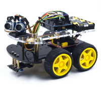
Related Product


Tesca specialize in doing turnkey projects that is fully operable when it is handed over to the project authority. Starting from inception to application training, Tesca provides the services as ONE source solution. Working side by side with government authorities and people across the World, we help countries to perform better. We support countries grow their economies, strengthen their education and health systems and improve financial management. We do this by providing consultancy & training in environment safety, education, health strengthening.
Category
Useful Links
Contact Us
International Sales:
 91-9829132777
91-9413330765
India Sales:
91-9588842361
2026 © All Rights Reserved.