
IoT Sensor Circuit Trainer
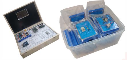
SPECIFICATION
IoT Sensor Circuit Trainer
- To understand the basic theory of internet of things (IoT) system.
- Design and implementation of sensor circuit.
- Ability to research and to develop the sensor circuit.
- Familiar with the applications of high accuracy sensor circuit.
Curriculum Outline:
- Design and implementation of photo and switch sensor circuits.
- Design and implementation of temperature and humidity sensor circuits.
- Design and implementation of infrared and gas sensor circuits.
- Design and implementation of ultrasonic and color sensor circuits.
Specification:
- Module One:
- Chapter 1: Photo Sensor Circuits
- Experiment 1: CdS Sensor Circuit:
- Operating Wave length: 500 nm - 580 nm
- Experiment 2: Photo Diode circuit:
- Operating Wave length: 760nm - 1000 nm
- Experiment 3: Phototransistor Circuit:
- Operating Wave length: 430nm - 670 nm
- Experiment 4: Photo Interrupter Circuit:
- Operating Wave length: 940 nm
Module Two:
- Chapter 2: Switch Sensor circuit:
- Experiment 1: Tilt Switch Circuit:
- Conduction Angel: 55-125 deg.
- SW Normal State: ON
- Operating State: LED Indicator
- Experiment 2: Micro Switch Circuit:
- SW Normal State: OFF
- Operating State: LED Indicator
- Experiment 3: Touch Switch Circuit:
- SW Normal State: OFF
- Operating State: LED Indicator
- Experiment 4: Reed Switch Circuit:
- SW Normal State: OFF
- Operating State: LED Indicator
- Experiment 5: Vibration Switch Circuit:
- SW Normal State: ON
- Operating State: LED Indicator
Module Three:
- Chapter 3: Temperature Sensor circuit:
- Experiment 1: MCP9701 Temperature Sensor Circuit
- Measurement Range: -40°C to +125°C
- Accuracy (max.): ± 4°C@ (0°C to + 70°C)
- Experiment 2: LM335 Temperature Sensor Circuit:
- Measurement Range: - 40°C to +100°C
- Accuracy (max.): ±2°C @ (25°C)
- Experiment 3: TC620 Temperature Sensor Circuit:
- Measurement Range: 0°C to +70°C
- Accuracy (max.): ±2°C
- Experiment 4: TC74 Temperature Sensor Circuit:
- Measurement Range: -40°C to +125°C
- Accuracy (max.): ± 3°C @ (0°C to+ 125°C)
Module Four:
- Chapter 4: Humidity Sensor Circuits:
- Experiment 1: H25K5A Humidity Sensor Circuit:
- Measurement Range: 20% - 90% RH
- Accuracy (max.): ±5% RH@25°C
- Experiment 2: SI7007 Humidity Sensor Circuit:
- Measurement Range: 0 - 100% RH
- Accuracy (max.): ±5% RH@ (0 - 80% RH)
- Experiment 3: RH818 Humidity Sensor Circuit:
- Measurement Range: 0 - 100% RH
- Accuracy (max.): ±1% RH@ (10%- 90% RH)
- Experiment 4: DHT11 Humidity Sensor Circuit:
- Measurement Range: 20% - 90% RH
- Accuracy (max.): ±5% RH@ 25°C
Module Five:
- Chapter 5 Infrared Sensor Circuits:
- Experiment 1: RE200B Passive Infrared Sensor Circuit:
- Frequency Response: 0.3 Hz - 3 Hz/±10 dB
- Field of View: 21 ° - 159° (X axis), 27.5° - 152.5° (Y axis)
- Experiment 2: OTP-628 Thermopile Infrared Sensor Circuit:
- Thermopile Voltage: 2.6±0.8 mV
- Field of View: 45 ° - 135 ° (X axis), 45° - 135° (Y axis)
- Experiment 3: TS-S2NMB Thermopile Infrared Sensor Circuit:
- Thermopile Voltage: 2.43±0.6 mV
- Field of View: 45 ° - 135° (X axis), 45° - 135° (Y axis)
Module Six:
- Chapter 6 Gas Sensor Circuits:
- Experiment 1: Smoke Sensor Circuit
- Sensing Body Resistance: 1 kΩ - 10 kΩ (1000 ppm lsobutane)
- Operating Humidity: <95% RH
- Operating Oxygen Concentration (min.): >2%
- Experiment 2: Nature Gas Sensor Circuit:
- Sensing Body Resistance: 2 kΩ - 20 kΩ (5000 ppm Methane)
- Operating Humidity: <95% RH
- Operating Oxygen Concentration (min.): > 2%
- Experiment 3: Alcohol Sensor Circuit:
- Sensing Body Resistance: 100.kΩ - 500 kΩ (100 ppm Alcohol)
- Operating Humidity: <95% RH
- Operating Oxygen Concentration (min.): > 2%
- Experiment 4: Carbon Monoxide Sensor Circuit:
- Sensing Body Resistance: 2 kΩ - 20 kΩ (100 ppm Carbon Monoxide)
- Operating Humidity: <95% RH
- Operating Oxygen Concentration (min.): > 2%
Module Seven:
- Chapter 7: Ultrasonic Sensor Circuits:
- Experiment 1: Sound Generator:
- Frequency: 850±100 Hz And 1700±150 Hz
- Experiment 2: Ultrasonic Transmitter:
- Operating Frequency: 40 kHz
- Operating Temperature: -20°C ~ +70°C
- Operating Humidity: <90% RH@40°C
- Experiment 3: Ultrasonic Receiver:
- Operating Frequency: 40 KHz
- Operating Temperature: -20°C ~ +70°C
- Operating Humidity: <90% RH@40°C
Module Eight:
- Chapter 8 Color Sensor Circuits:
- Experiment 1: Red Sensor Circuit
- Operating Wave length: 590 nm ~ 720 nm (?p: 660 nm)
- Experiment 2: Green Sensor Circuit:
- Operating Wave length: 480 nm ~ 660 nm (?p: 540 nm)
- Experiment 3: Blue Sensor Circuit:
- Operating Wave length: 400 nm ~ 540 nm (?p: 460 nm)
- Function Generator and DC Power Supply:
- Waveforms: Sine, Triangle Square, TTL Pulse
- Amplitude: >10Vpp Impedance: 50ohm±10 percent
- Duty Control: 30 percent ~ 60 percent
- Display: 6 Digit LED display
- Frequency Range: 10HZ to 100 kHz (4 Ranges)
- Frequency Range: 100HZ to 1 MHz (4 Ranges)
- Constant Voltage Output: ±5V, ±12V
- Variable Voltage Output: 0V ~ ±15V
- Power source: 220 to 230V AC, 50HZ, 1 Phase
Enquiry Form
Related Product


Tesca specialize in doing turnkey projects that is fully operable when it is handed over to the project authority. Starting from inception to application training, Tesca provides the services as ONE source solution. Working side by side with government authorities and people across the World, we help countries to perform better. We support countries grow their economies, strengthen their education and health systems and improve financial management. We do this by providing consultancy & training in environment safety, education, health strengthening.
Category
Useful Links
Contact Us
International Sales:
 91-9829132777
91-9413330765
India Sales:
91-9588842361
2026 © All Rights Reserved.