
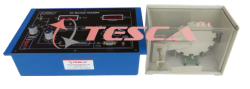
Lift Simulator
Order Code: 22235521.2.31
Category: General Lab Equipment I
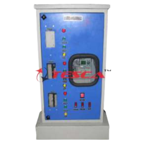
Specifications: The power supply is 24VDC, the maximum current 1A. The magneto-thermal protections are circuit devices inside the module. It is composed of a cabin M that performs the function of uphill and downhill on the floors. The pos...
SPECIFICATION
Specifications:
- The power supply is 24VDC, the maximum current 1A.
- The magneto-thermal protections are circuit devices inside the module.
- It is composed of a cabin M that performs the function of uphill and downhill on the floors.
- The position of the cabin, during uphill and downhill, is detected by 5 NO limit switches (micro switch: M0, M1, M2, MD, MU). The first three (M0, M1, M2) detect the floors according to the following order: M0 for the il ground floor, M1 for the first floor, M2 for the second floor. The remaining two limit switches (MD - MU) are, respectively, the first one for the safety of the overrun downward and the second one for the safety of the overrun upward.
The panel of the module consists of:
- ¾ 3 NO pushbuttons for calling to the floor, named P0, P1 and P2 (P0 ground floor, P1 first floor and P 2 second floor).
- ¾ 3 green LED (floor presence): F0, F1 and F2 (F0 ground floor, F1 first floor and F2 second floor).
- ¾ In the “lift cabin” section, we have the NO pushbuttons named: C0, C1 and C2, which replicate the function of the pushbuttons named P0, P1 and P2. In the same section, we also have the green LED, named: F0, F1 and F2, and the red LED, named: up, down and DO.
Enquiry Form
Related Product
Tesca specialize in doing turnkey projects that is fully operable when it is handed over to the project authority. Starting from inception to application training, Tesca provides the services as ONE source solution. Working side by side with government authorities and people across the World, we help countries to perform better. We support countries grow their economies, strengthen their education and health systems and improve financial management. We do this by providing consultancy & training in environment safety, education, health strengthening.
Category
Useful Links
Contact Us
International Sales:
export@tesca.in
 91-9829132777
91-9413330765
India Sales:
indiasales@tesca.in
91-9588842361
2026 © All Rights Reserved.