
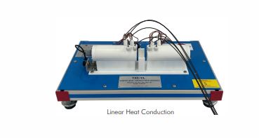
Linear Heat Conduction
Order Code: 23247057.1
Category: General Lab Equipment III
SPECIFICATIONS:- Unit A Bench-top unit to study the principles of linear heat conduction and to allow the conductivity of various solid conductors and insulators to be measured. It is given with interchangeable samples of different materi...
SPECIFICATION
SPECIFICATIONS:-
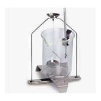
Unit A
- Bench-top unit to study the principles of linear heat conduction and to allow the conductivity of various solid conductors and insulators to be measured.
- It is given with interchangeable samples of different materials, different diameters, and different insulating materials that allow to demonstration the area effects, the conductivity and the combinations in series in the heat transfer process.
- Anodized aluminum frame and panels made of painted steel.
- Diagram in the front panel with the distribution of the elements similar to the real one.
- Input heat section.
- Electric heater, computer controlled.
- Refrigeration section with a surface cooled by water. Interchangeable central sections:
- With brass of 25 mm of diameter.
- With brass of 10 mm of diameter.
- With stainless steel of 25 mm of diameter.
- Flow sensor to measure the cooling water flow, range:
- 0.25-6.5 l/min.
- Water flow regulation valve.
- Thermal paste is supplied to demonstrate the difference between poor and good thermal contact between the sections.
- 19 Temperature sensors, "T" type (high precision): 17 Temperature sensors distributed in the heating section (4 sensors), refrigeration section (4 sensors) and central sections (3 sensors in each central section).
- Temperature sensor at the water inlet of the unit.
- Temperature sensor at the water outlet of the unit.
- Power measurement from the computer.
- ables and Accessories, for normal operation.
- This unit is supplied with 8 manuals: Required Services, Assembly and Installation, Interface and Control Software, Starting-up, Safety, Maintenance, Calibration & Practices Manuals.
- PID Computer Control + Data Acquisition + Data Management Software:
- Compatible with actual Windows operating systems.
- Graphic and intuitive simulation of the process in screen. Compatible with the industry standards. Registration and visualization of all process variables in an automatic and simultaneous way.
- Flexible, open and multicontrol software, developed with actual windows graphic systems, acting simultaneously on all process parameters.
- Analog and digital PID control.
- Menu for PID and set point selection required in the whole work range.
- Management, processing, comparison and storage of
- Sampling velocity up to 250 KS/s (Kilo samples per second). Calibration system for the sensors involved in the
- process. It allows the registration of the alarms state and the graphic representation in real time.
- Comparative analysis of the obtained data, after the process and modification of the conditions during the
- process. Open software, allowing to the teacher to modify texts, instructions. Teacher's and student's passwords to facilitate the teacher's control on the student, and allowing the access to different work levels. This unit allows the 30 students of the classroom to visualize simultaneously all results and manipulation of the unit, during the process, by using a projector or an electronic whiteboard. -This module requires Control Interface Box and Data
- Acquisition Board (DAB).
b) Control Interface
- The Control Interface Box is part of the SCADA system.
- Control interface box with process diagram in the front panel. The unit control elements are permanently computer controlled.
- Simultaneous visualization in the computer of all
- parameters involved in the process. Calibration of all sensors involved in the process. Real time curves representation about system
- responses. All the actuators' values can be changed at any time from the keyboard allowing the analysis about curves and responses of the whole process.
- Shield and filtered signals to avoid external interferences. Real time PID control with flexibility of modifications from the computer keyboard of the PID parameters, at any moment during the process. Real time PID control for parameters involved in the
- process simultaneously.
- Proportional control, integral control and derivative control, based on the real PID mathematical formula, by changing the values, at any time, of the three control constants (proportional, integral and derivative
- constants). Open control allowing modifications, at any moment and in real time, of parameters involved in the process simultaneously,
- Three safety levels, one mechanical in the unit, another electronic in the control interface and the third
- one in the control software.
- The complete unit includes as well:
- Advanced Real-Time SCADA and PID Control.
- Open Control + Multicontrol + Real-Time Control. Specialized Control Software based on LabVIEW OR SIMILAR. National Instruments Data Acquisition board (250 KS/s, kilo samples per second).
- Calibration exercises, which are included, teach the user how to calibrate a sensor and the importance of checking the accuracy of the sensors before taking measurements.
- Projector and/or electronic whiteboard compatibility allows the unit to be explained and demonstrated to an entire class at one time.
- Capable of doing applied research, real industrial simulation, training courses, etc.
- Remote operation and control by the user and remote control for technical support, are always included. Totally safe, utilizing 4 safety systems (Mechanical,
- Electrical, Electronic & Software). Designed and manufactured under several quality standards.
- Optional ICAI software to create, edit and carry out practical exercises, tests, exams, calculations, etc. Apart from monitoring user's knowledge and progress reached.
- This unit has been designed for future expansion and integration. A common expansion is the Scada-Net (ESN) System which enables multiple students to simultaneously operate many units in a network.
c)DAB. Data Acquisition Board:
- The Data Acquisition board is part of the SCADA system.
- PCI Express Data acquisition board (National Instruments) to be placed in a computer slot.
- Analog input: Channels 16 single-ended or 8 differential. Resolution 16 bits, 1 in 65536. Sampling
- rate up to: 250 KS/s (kilo samples per second). Analog output: Channels=2. Resolution 16 bits, I in 65536.
- Digital Input/Output: Channels-24 inputs/outputs. The Data Acquisition board model may change at any
- moment, providing the same or better features than those required for the unit.
- Cables and Accessories, for normal operation.
Manuals:
This unit is supplied with 8 manuals: Required Services, Assembly and Installation, Interface and Control Software, Starting-up, Safety, Maintenance, Calibration & Practices Manuals.
EXERCISES AND PRACTICAL POSSIBILITIES TO BE DONE WITH THE MAIN ITEMS
1.- Conduction through a simple bar.
2.- Conduction through a compound bar.
3.- Determination of the thermal conductivity "k" of different materials (conductors and insulators).
4. The thermal conductivity properties of insulators may be found by inserting paper or other elements between the heating and cooling sections.
5.- Insulation effect.
Ric
6.- Determination of the thermal contact resistance
7.- Effect of the crossing sectional area.
8.- Understanding the use of the Fourier equation in determining rate of heat flow through solid materials.
Additional practical possibilities:
9.- Sensors calibration.
Other possibilities to be done with this Unit: 10. Many students view results simultaneously.
To view all results in real time in the classroom by means of a projector or an electronic whiteboard. 11. Open Control, Multicontrol and Real Time Control.
This unit allows intrinsically and/or extrinsically to change the span, gains; proportional, integral, derivative parameters; etc, in real time.
12.- The Computer Control System with SCADA and PID Control allow a real industrial simulation.
13.- This unit is totally safe as uses mechanical, electrical/electronic, and software safety devices.
14- This unit can be used for doing applied research.
15.- This unit can be used for giving training courses to Industries even to other Technical Education Institutions.
16.- Control of the unit process through the control interface box without the computer.
17.- Visualization of all the sensors values used in the unit process.
- By using PLC-PI additional 19 more exercises can be done.
Several other exercises can be done and designed by the user.
2 PLC. Industrial Control using PLC (it includes PLC- PI Module plus PLC-SOF Control Software):
-PLC-PI. PLC Module:
Metallic box.
Circuit diagram in the module front panel.
Digital inputs (X) and Digital outputs (Y) block: 16 Digital inputs. 14 Digital outputs.
Analog inputs block: 16 Analog inputs.
Analog outputs block: 4 Analog outputs.
Touch screen.
Panasonic PLC:
High-speed scan of 0.32 µsec. Program capacity of 32 Ksteps. High-speed counter. Multi-point PID control.
Digital inputs/outputs and analog inputs/outputs Panasonic modules.
- PLC Control Software:
For this particular unit, always included with PLC
supply. Practices to be done with PLC-PI
1.- Control of the particular unit process through the control interface box without the computer.
2.- Visualization of all the sensors values used in the particular unit process.
3.- Calibration of all sensors included in the particular unit process.
4.- Hand on of all the actuators involved in the particular unit process.
5.- Realization of different experiments, in automatic way, without having in front the particular unit. (These experiments can be ) decided previously .
6.- Simulation of outside actions, in the cases do not exist hardware elements. (Example: test of complementary tanks, complementary industrial environment to the process to be studied, etc).
7.- PLC hardware general use.
8.- PLC process application for the particular unit.
9.- PLC structure.
10.-PLC inputs and outputs configuration.
11.-PLC configuration possibilities.
12.-PLC program languages.
13.-PLC different programming standard languages (ladder diagram (LD), structured text (ST), instructions list (IL), sequential function chart (SFC), function block diagram (FBD)).
14.-New configuration and development of new process.
15.-Hand on an established process.
16.-To visualize and see the results and to make comparisons with the particular unit process.
17.-Possibility of creating new process in relation with the particular unit.
18.-PLC Programming Exercises.
19.-Own PLC applications in accordance with teacher and student requirements.
Enquiry Form
Related Product
Tesca specialize in doing turnkey projects that is fully operable when it is handed over to the project authority. Starting from inception to application training, Tesca provides the services as ONE source solution. Working side by side with government authorities and people across the World, we help countries to perform better. We support countries grow their economies, strengthen their education and health systems and improve financial management. We do this by providing consultancy & training in environment safety, education, health strengthening.
Category
Useful Links
Contact Us
International Sales:
 91-9829132777
91-9413330765
India Sales:
91-9588842361
2026 © All Rights Reserved.