
LOSSES IN PIPING SYSTEMS
Order Code: 22235750.28
Category: General Lab Equipment II
Key Features: Mobile, space-saving panel that includes the common pipework parts used in domestic heating systems Includes two colour-coded water circuits Works with Digital Hydraulic Bench for easy installation Includes diff erent p...
SPECIFICATION
Key Features:
- Mobile, space-saving panel that includes the common pipework parts used in domestic heating systems
- Includes two colour-coded water circuits
- Works with Digital Hydraulic Bench for easy installation
- Includes diff erent pipe bends and valves to compare losses
- Fitted with a range of piezometers and a pressure gauge to give accurate pressure measurement
- Optional ‘roughened pipe’ ancillary to investigate flow characteristics in a roughened pipe
Learning Outcomes:
A comprehensive range of investigations into losses in a variety of pipes and pipe system components.
Including:
- Straight pipe loss
- Sudden expansion
- Sudden contraction
- Bends with diff erent radii
- Valves
- Elbows
- Flow in a roughened pipe – needs the optional Roughened Pipe
Key Specifications
- Two circuits
- Sudden expansion and contraction
- Gate valve and globe valve
- Elbow
- Mitre bend
- Three smooth 90-degree bends
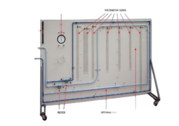
Description
The Losses in Piping Systems apparatus is a vertical panel with two separate hydraulic circuits, colour-coded for clarity. Each circuit includes various pipe system components. The unit has wheels for mobility, which also help when storing the apparatus. The Digital Hydraulic Bench (available separately) supplies each circuit with a controlled flow of water. This allows students to study fl ow through the various pipe forms and components, and study and compare the pipe and component characteristics.
The circuits are made of small-bore copper pipe, used in a wide variety of applications such as domestic centralheating systems. The small bore allows the circuits to include many pipe bends and components, while preserving eff ective upstream and downstream test lengths. To measure pressure loss across components, the panel includes
piezometer tubes and a pressure gauge. The pressure gauge measures pressure loss across valves; the piezometer tubes measure pressure loss across the other components. Included is a hand-pump to adjust the datum position of the piezometers. Both circuits have common inlet and outlet pipes, controlled by valves.
The valves are at the outlet to minimise fl ow disruption.The optional ‘roughened pipe’. This can fit to the Losses in Piping Systems apparatus or be used by itself (fi tted to a wall and connected to a hydraulic bench). It includes a pipe with a roughened internal bore, and pressure tapping points connected to a manometer. The manometer measures the pressure drop due to the pipe. Students compare their experimental results with Moody and Nickuradse charts.
Standard Features:
- Supplied with a comprehensive user guide
- Five-year warranty
- Manufactured in accordance with the latest European Union directives
- ISO9001 certified manufacturer
Essential Base Unit
• Digital Hydraulic Bench
This product will also work with existing Gravimetric and Volumetric Hydraulic Benches
Typical Work Assignments
Globe and Gate Valve Loss Coefficients
This experiment takes results of the pressure losses across the two valves at diff erent fl ow
rates and converts them to loss coeffi cient (K) values for comparison. The chart compares
them by plotting the results against percentage fl ow rate.
Elbow and Mitre Head Loss
This experiment compares the losses across the elbow and mitre bends at diff erent fl ow rate and converts them to bend loss (hB) by excluding other losses.
The chart compares them by plotting the results against V2/2g which produces fairly linearresults.
Detailed Specification –
Is committed to a programme of continuous improvement; hence we reserve the right to alter the design and product specifi cation without prior notice.
Nett dimensions and weight:
2600 mm x 800 mm x 1700 mm, and 95 kg
Approximate packed dimensions and weight:
4.3 m3 and 150 kg
Parts:
- Small-bore straight pipe (nominally 13.6 mm bore copper)
- Larger-bore straight pipe (nominally 26.2 mm bore copper)
- Sudden expansion (13.6 mm to 26.2 mm)
- Sudden contraction (26.2 mm to 13.6 mm)
- 90-degree mitre bend (no radius)
- Elbow (13.6 mm radius)
- Small radius, smooth 90° bend (50 mm radius)
- Medium radius, smooth 90° bend (100 mm radius)
- Large radius, smooth 90° bend (150 mm radius)
- Gate valve and Globe valve
Detailed Specification:
Is committed to a programme of continuous improvement; hence we reserve the right to alter the design and product specifi cation without prior notice.
Nett dimensions and weight:
1200 mm x 200 mm x 200 mm, and 3 kg
Approximate packed dimensions and weight:
0.05 m3 and 5 kg
Internal coating thickness:
300 m to 600 m
Pipe diameter:
19 mm
Space needed
Fitted to the 1.5 m x 0.3 m of wall
Operating Conditions
Operating environment:
Laboratory
Storage temperature range:
–25°C to +55°C (when packed for transport)
Operating temperature range:
+5°C to +40°C
Operating relative humidity range:
80% at temperatures < 31°C decreasing linearly to 50% at 40°C
Enquiry Form
Related Product


Tesca specialize in doing turnkey projects that is fully operable when it is handed over to the project authority. Starting from inception to application training, Tesca provides the services as ONE source solution. Working side by side with government authorities and people across the World, we help countries to perform better. We support countries grow their economies, strengthen their education and health systems and improve financial management. We do this by providing consultancy & training in environment safety, education, health strengthening.
Category
Useful Links
Contact Us
International Sales:
 91-9829132777
91-9413330765
India Sales:
91-9588842361
2026 © All Rights Reserved.