
Measurement of Magnetoresistance in Bismuth
Order Code: 55532B
Category: Physics Trainers
It is noticed that the resistance of the sample changes when the magnetic field is turned on. The phenomenon , called magnetoresistance, is due to the fact that the drift velocity of all the carriers is not same. With the magnetic eld on; ...
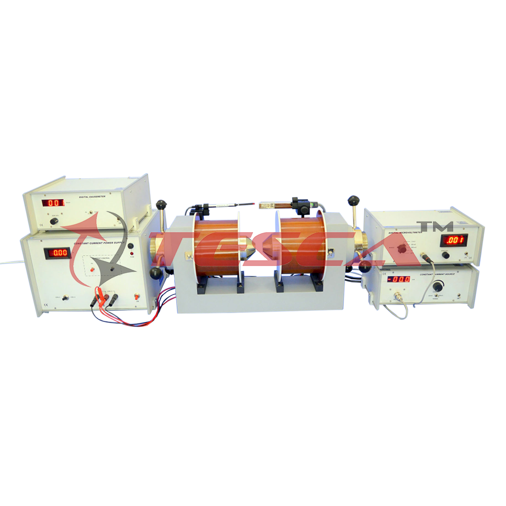
SPECIFICATION
- Hall Probe: Bismuth
- Constant Current Source
- Digital Microvoltmeter
- Electromagnet (Specifications as per datasheet attached)
- Constant Current Power Supply (Specifications as per datasheet attached)
- Digital Gaussmeter (Specifications as per datasheet attached)
- Range : 0-20mA, 0-200mA
- Resolution : 10µA
- Accuracy : ±0.25% of reading ±1 digit
- Display : 3½ digit, 7 segment LED with autopolarity and decimal indication
- Range : 1mV, 10mV, 100mV, 1V & 10V with 100% over-ranging.
- Resolution : 1pV
- Accuracy : ±0.2% ±1 digit
- Stability : Within ±1 digit
- input Impedance : >1000MW (10MW on 10V range)
- Display : 3½ digit, 7 segment LED with autopolarity and decimal indication
Enquiry Form
Related Product


Tesca specialize in doing turnkey projects that is fully operable when it is handed over to the project authority. Starting from inception to application training, Tesca provides the services as ONE source solution. Working side by side with government authorities and people across the World, we help countries to perform better. We support countries grow their economies, strengthen their education and health systems and improve financial management. We do this by providing consultancy & training in environment safety, education, health strengthening.
Category
Useful Links
Contact Us
International Sales:
 91-9829132777
91-9413330765
India Sales:
91-9588842361
2026 © All Rights Reserved.