
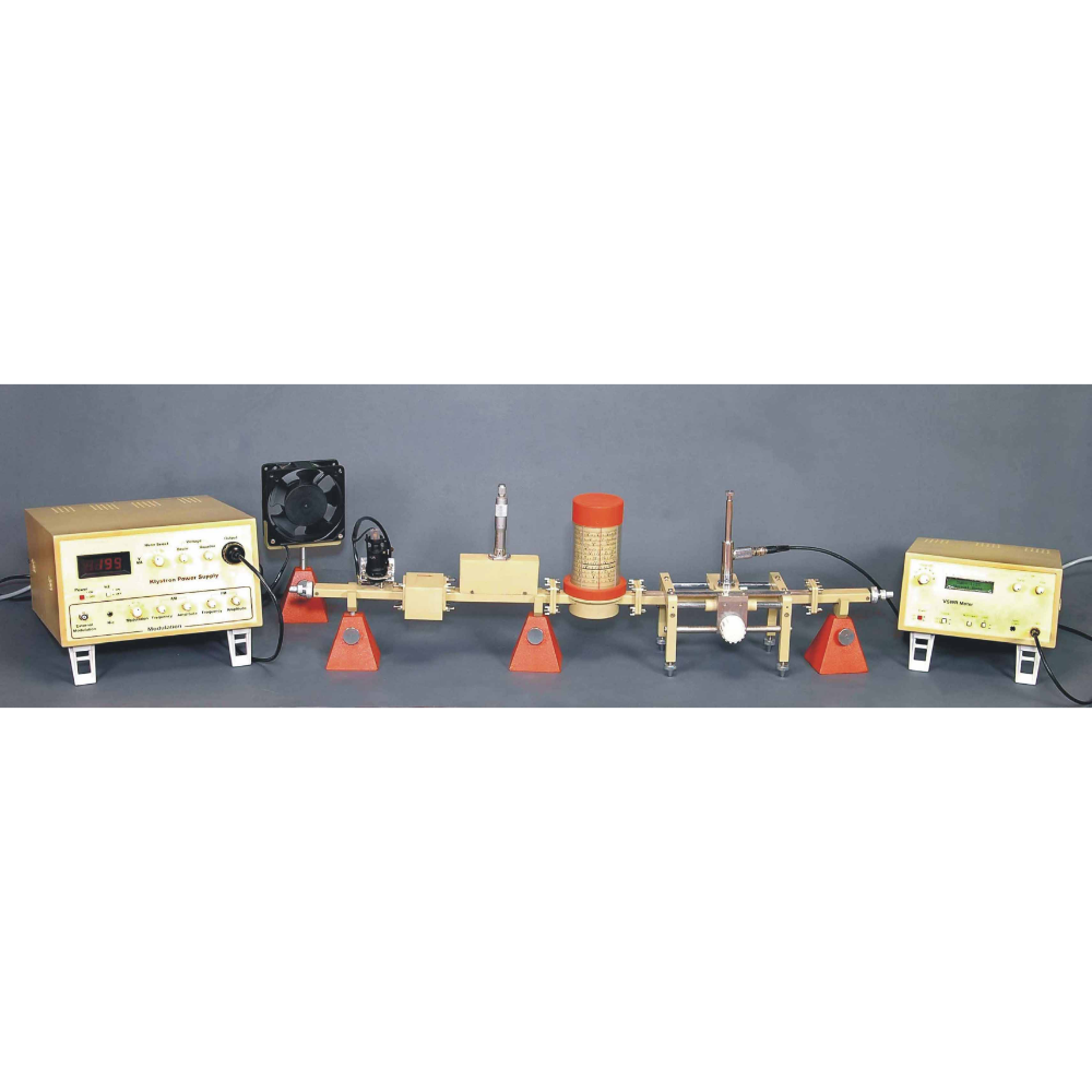
Microwave Experimental Trainer
Order Code: 19203364.6
Category: General Lab Equipment III
Slide Screw Transformer: Displacement range 65 mm Displacement resolution 0 1 mm Pin penetration depth 0 approx 10 nit Waveguide type R100 Length 182 mm Weight 650 g E-Field Probe: Detector type. Schottky. Connecton BNC socket Length 295 m...
SPECIFICATION
- Slide Screw Transformer: Displacement range 65 mm Displacement resolution 0 1 mm Pin penetration depth 0 approx 10 nit Waveguide type R100 Length 182 mm Weight 650 g
- E-Field Probe: Detector type. Schottky. Connecton BNC socket Length 295 mm.
- Gunn Oscillator: Gunn diode module, length 27 mm Rear housing wan Diaphragm with aperture 8 mill diameter Wavegulde adapter 32 mm Varactor tuning unit (movable short in a frequency range 8 5 GHz I 1 GHz Aluminium Gunn diode module Waveguide Napier with quick connectors Operating voltage 8 10 V DC Current consumption approx 120 mA Operating frequency 9 40 GHz Microwave power 10 mid, hip 15 mid Connection BNC socket Waveguide type R100
- Coax Detector: Frequency range 001 GHz 10 Griz Input (RF) RF plug N senes Output (video) BNC socket Output polarity negative Impedance 50 Ohm Internal DC return
- PIN Modulator: Aluminium module with quick connectors f0 = 9 40 GHz Insertion loss aT approx_ 1 dB. Back reflection loss aR approx i5 dB. Operation voltage : 0...1.0 V DC. Current consumption _ 0...10 mA Modulation frequency : 5 MHz Connection : BNC socket Waveguide type RICO.
- Unidirectional Line: Wavegulde with feint element I = 9 40 GHZ Isolation 20 dB Insertion loss 1 5 dB SWR 1 25 Waveguide type : R I00
- Variable Attenuator: Attenuation 20 dB (ca) ) Calibration 3 dB and 10 dB fa 9 40 GHz Waveguide type - R100 Length 120 mm Weight 650 g
- Moveable Short: SWR approx 50 dB at 9.4 GHz. Frequency range : 8_2 GHz 12 4 GHz. Shift range 25 mm. Accuracy of reading ± 0.01 mm. Waveguide type • R100 Length of waveguide approx 80 mm.
- Waveguide 200 mm Aluminium waveguide Waveguide type R100
- Waveguide Termination Reflection factor r = 0.02 (- 35 dB) at 9.40 GHz. r = 0.03 (- 30 dB) at 8 12 GHz. Waveguide type: R100 Length: 85 ran
- Gross Directional Coupler: Coupling loss approx 20 30 dB depending on the coupling aiaphragm Directional loss approx 10...20 dB depending on the coupling diaphragm Waveguide type R100 Dimensions 60 x 60 x 56 min Weight 400 g
- Waveguide Propagation Accessories: 1 shod-circuit plate 1 diagram vath aperture. 6 mm diameter I diaphragm with aperture. 7 nin diameter 1 diaphragm with aperture. 8 nun diameter I diaphragm with aperture. 9 mm diameter I diaphragm with aperture. 10 mm diameter I holder I diaphragm with slits 2 x 10 mm. 0 degrees 1 diaphragm with slits 2 x 10 mm. 90 degrees 1 diaphragm with slits 2 x 15 mm. 45 degrees I diaphragm with slits 2 x 15 mm. 90 degrees
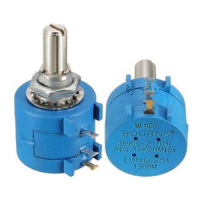
- GUNN POWER SUPPLY: Gunn voltage - 10 V UG 0 V adjustable 10-turn potentiometer. shod-circuit proof. Gunn current max 200 mA Display D 10 V. 0 200 mA. LED display for selected scale. Movement class 1.5 with mirror scale GUNN DC supply of the Gunn oscillator kV for recording characteristics using an XY recorder. DOPPLER OUT for experiments with Doppler radar. MOD IN - for direct modutabon of the Gunn oscillator, input signal max ± 10 V
- PIN MODULATOR: Clock oscillator 976 Hz. 0 5 V. 0 10 rnA, shod-circuit proof PIN toggle switch position determines internal modulation through the clock oscillator or for external modulabon MOD for external modulabon of the PIN modulator, input signal max ± 10 V
- HOMODYNE SWR METER: Principle Lock-in detection with internal synchronization through the clock oscillator Dynamic range 0 55 aB can be set in 12 steps Additional 5 dB available via vanable gain Sensitivity I pVrms for full scale deflection Accuracy 0 3 dB over the whole range Mid-frequency 976 Hz Bandwidth 10 Hz Display Power scale + 0 5 dB - 20 dB (calibrated in re for square-law detectors) SWR scale 100 5 Linear scale 0 100 % (0 dB corresponds to 100 %) Movement class 15 with mirror scale Inputs/outputs INPUT unbiased, impedance 10 kOhm AMP OUT DC output for the measurement voltage
- MOD Inputsioutputs: INPUT jointly for ANALOG and TTL. impedance 50 Ohm ANALOG OUT: analog signal mar t 2 V. bandvadth 1 MHZ. gain approx. 30 TTL OUT TTL levet All in-/outputs are connected with BNC sockets. Mains connection 115/230 V. 50 Hz, approx. 20 VA with mains connection cable and earthing-pin plug. Dimensons : 500 x 330 x 150 mm (L x W x H) Weight : appear 8 kg
- Transition Waveguide/Coax: Conversion from TE 10 wavegiode waves into TEM waves and viceversa Connection of the coax detector SWR . 1 I 25 Frequency range 8 2 GHz 12 4 GHz Waveguide type Mtn
- Fixed Attenuator: - Lower microwave power to a fixed magnitude Utilized for the protection of sensitive elements or for Me decouping of Circuit components. Design Aluminium module Attenuation 10 dB. Waveguide type R100. Length 25 mm Thumb screw M4. set of 10 -For the connection of waveguicle components
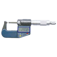
- Slotted Measuring Line . Displacement range . 65 mm. Displacement resolution . 0 1 mm. Penetration depth of the measurement probe : 2 mm Output RF socket N series. Waveguide type . RICO. Length : 182 mm Weight 600 g.
- 3-Screw Transformer: Met Frequency range : 8.2 Gliz...12.4 Wavegulde type . R100. Length 45 mm. Weight : 150 g. Suppord for
- Waveguide Components: 1 stand rod 180 mm long. with thread M6 1 stand rod 245 mm long. with thread M6
- Stand base MF: Socket for 4-mm plugs Span width for vertical roas max 13 mm dr % inch Bore for base rods each 10 mm diameter bores- each 4 mm dtameter Dimensions 18 5 an x 4 an x 3 5 an BNC cable 2 m Plugs BNC 1 BNC. Impedance 50 Screened cable BNC/4 mm Coaxial able with a separate connecting plug for screening. Impedance 80 Cable capacitance 120 pF. Length 1 15m.
- PERSONAL COMPUTER WITH OPERATING SYSTEM WINDOWS 10/LATEST VERSION Latest versa) Intel core 4GB RAM 1TB HDO. Intel HD Graphics 520. 20 monitor. Connectors in full set
Enquiry Form
Related Product


Tesca specialize in doing turnkey projects that is fully operable when it is handed over to the project authority. Starting from inception to application training, Tesca provides the services as ONE source solution. Working side by side with government authorities and people across the World, we help countries to perform better. We support countries grow their economies, strengthen their education and health systems and improve financial management. We do this by providing consultancy & training in environment safety, education, health strengthening.
Category
Useful Links
Contact Us
International Sales:
 91-9829132777
91-9413330765
India Sales:
91-9588842361
2026 © All Rights Reserved.