
MICROWAVE LABORATORY

Order Code: 23246810.8
Category: General Lab Equipment II
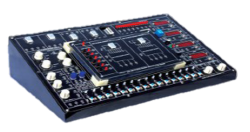
The MICROWAVE LABORATORY is designed to study and test waveguide electronics and components used in the field of microwaves. In detail, it is possible to analyze and carry out experiments in the principal aspects of microwaves and their application t...
SPECIFICATION
The MICROWAVE LABORATORY is designed to study and test waveguide electronics and components used in the field of microwaves. In detail, it is possible to analyze and carry out experiments in the principal aspects of microwaves and their application to communication systems:
• Active and passive components
• Waveguides and antennas for microwaves
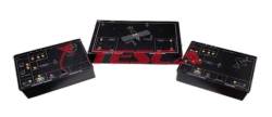
• Audio/Video/Data communication systems and Measurements on microwaves. The laboratory consists of a main system and an optional accessory: 1
• Waveguides, Antennas and Microwave Audio/Video communication System. It enables to study and test lines, antennas and transmissions used in the field of microwaves and to carry out a complete microwave radio link for the transmission and reception of an Audio/Video signal. 2
• Gunn Kit. system that uses a Gunn diode mounted on a cavity as RF source in microwaves. 3
• Satellite Transponder Kit: is a system that simulates a satellite transponder; it consists of active and passive devices working on the same kind of Ku-band employed in commercial satellite communications. In detail, it is possible to analyze and to experiment, the following main aspects of microwaves and their applications in communication systems:
• Microwave generation Complied 23246810.8
• Waveguide components
• Antennas for microwaves and their parameters
• Microwave propagation
• Measurements on microwave systems TRAINING PROGRAM (Laboratory guide manual )
• General microwave theory
• Overview of electronic devices and passive components of the laboratory
• Characteristics of: - microwave components - waveguide and flange - Horn antennas and parabolic reflector - reflection and polarization system
• Oscillator
• Frequency measurements
• Wavelength measurements in waveguide and free space
• Direct and reflected power measurements
• Power splitting and impedance mismatch measurement
• SWR and impedance measurement
• Impedance calculation with Smith’s chart
• Impedance matching
• Directional and T-hybrid couplers
• Gain and radiation diagram of microwave antennas
• Antenna Gain measurement: - comparison method - method of the two antennas
• Link attenuation • Passive repeaters (mirrors)
• Modulation and transmission of microwave signals
• Reception and demodulation of microwave signals
• Frequency conversion with local oscillator and mixer
• Audio/Video point-to-point communication system
• Audio/Video Satellite communication system: Analog satellite receiver required (not supplied)
• Audio/Data communication system and communication between PCs (with 1 or 2 optional modules mod. - not included)
• Heritage Audio Series Analog Summing Mixers
• Doppler Radar: more antennas are used and the relationship between the object speed and the doppler signal is complied with. MICROWAVE WAVEGUIDES, ANTENNAS AND AUDIO/VIDEO COMMUNICATION SYSTEM TECHNICAL SPECIFICATION
• Operating frequency: -
10750, 10777, 10804, 10831 MHz - X and Ku band, - 4 channels with PLL frequency generation
• TX/RX link frequencies: 10750 or 10777 MHz
• Silver-plated internal waveguide
• 2 waveguides – coaxial adapter
• 3 straight-line waveguides (WG)
• 1 WG frequency-meter: - Range: about 10500 to 11000 MHz - Calibration report: 21 points inside the frequency range with 25 MHz steps and 4 points on the 4 output frequencies (10750, 10777,10804, 10831 MHz) • 1 WG slotted line
• 1 WG variable attenuator of 30 dB • 2 WG fixed attenuators of 3 dB and 6 dB
• 1 coax fixed attenuator: - 50 Ω impedance - SMA/SMA connectors - Range: DC to 3000 MHz - 20dB Attenuation
• 3 WG Loading terminations: - 2 matched terminations of 1 W - 1 short-circuit termination
• 1 WG tuner/impedance matching unit E-H
• 1 Coax detector: - 50 Ω input - SMA/BNC connectors - Range: 10 to 12400 MHz - Max input level: +20 dBm - Negative polarity
• 1 WG 4 ports T-magic
• 1 WG directional coupler: - 3 ports - 20dB coupling
• 3 WG horn antennas: - 2 with 20 dB gain - 1 with 15 dB gain
• 1 parabolic antenna: - 0.36 m Diameter - f/D = 0.5 - Gain: 29.5 dB (theoretical)
• 2 reflector planes: - 1 with 180 X 180 mm - 1 with 300 X 300 mm
• 1 Polarization plane: - with 180 X 180 mm
• 2 conversion units: - Up converter: LO 8350 MHz, +15 Vdc power supply - Down converter: LO 8296 MHz, +15 Vdc power supply
• 6 (high and low) supports and connection cables
• 1 Rotary table with bearing scale
• Microphone
• Transmitter unit ( for training purpose ) including : -
Regulated power supply protected from short-circuit - Audio generator - Video bar generator - Audio/video input - Audio modulator - Audio/video combiner - IF converter
• Receiver unit including: - Regulated power supply protected from short-circuit - IF demodulator - Audio demodulator - Audio/Video output - Loudspeaker with audio amplifier and volume control - LCD colour Video Monitor
• VSWR/LEVEL Measuring unit including: - Regulated power supply protected from short-circuit - Power and VSWR meter - Rechargeable battery with charge indicator
• 2 ALU tray for storing components Power supply: 230 Vac 50 Hz single-phase - 90 VA (Other voltage and frequency under request) Dimensions: 620 x 460 x 230 mm (each tray) GUNN KIT TRAINING PROGRAM
• Gunn Diode Oscillator
• Gunn Transceiver: Gunn Oscillator and Schottky diode (mixer)
• Radar Experiment and frequency relation between the signal Doppler – object speed
TECHNICAL SPECIFICATION
• 1 WG horn Antenna suitable for Gunn Diode Oscillator: - Frequency: 10525 MHz - Gain: 12dB - Ray Amplitude: 70° ( E plane) / 30° ( H plane)
• Gunn diode oscillator frequency: 10525 MHz (X band)
• Gunn oscillator power output: +7 dBm SATELLITE TRANSPONDER KIT TRAINING PROGRAM:
• Overview of electronic devices and antennas making up a satellite transponder
• Frequency conversion: up converter and down converter
• Audio/Video Satellite communication system with Satellite Ku band repeater simulation.
TECHNICAL SPECIFICATION:
• Up-Link unit including: - IF Ku-band converter (14GHz) with output amplifier - WG horn antenna, 10 dB
• Satellite Transponder unit including: - receiver parabolic antenna with waveguide - coaxial adapter - Ku-band converter (14GHz-to-10,75GHz) - transmitter parabolic antenna with waveguide-coaxial adapter Technical Clauses: The bidder must present a manufacturers authorization Training manual for the items Product Demo CD/Video Demo + Smith Chart + Wall Charts + Theoretical /Experimentation Video Microwave Simulation Software with License The supplier must provide one week training to 15 trainers
Enquiry Form
Related Product

Tesca specialize in doing turnkey projects that is fully operable when it is handed over to the project authority. Starting from inception to application training, Tesca provides the services as ONE source solution. Working side by side with government authorities and people across the World, we help countries to perform better. We support countries grow their economies, strengthen their education and health systems and improve financial management. We do this by providing consultancy & training in environment safety, education, health strengthening.
Category
Useful Links
Contact Us
International Sales:
 91-9829132777
91-9413330765
India Sales:
91-9588842361
2026 © All Rights Reserved.