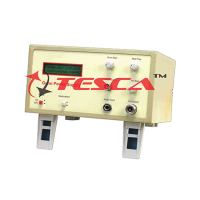
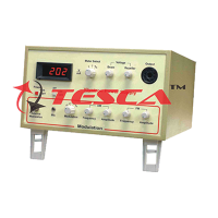
Microwave PowerMeter

Order Code: 10413
Category: Microwave Test Benches
Features: Low Cost for educational use with microwave bench 8.2 to 12.4GHz X band measurement range 0.1dB resolution Digital Display on backlit LCD with bargraph Wide range from +20dBm(100mW) to -30dBm(1uW) dB relative mode Measurem...
SPECIFICATION
Features:
- Low Cost for educational use with microwave bench
- 8.2 to 12.4GHz X band measurement range
- 0.1dB resolution
- Digital Display on backlit LCD with bargraph
- Wide range from +20dBm(100mW) to -30dBm(1uW)
- dB relative mode
- Measurement in dBm, mW, dBr, dBW, dBuW
- Shock/Drop resistant Thermistor Sensor
- In built X band source for scalar network analysis
Technical Specifications
Power Meter
- Frequency range : 8.2GHz to 12.4 Ghz
- Display : 16X2 Backlit LCD
- Power : +20dBm to -30dBm
- Measurement : dBm, dBr, mW, dBW, dBuWWith Digital Display
- Resolution : 0.1, 0.5 and 1dB
- Offset : For relative measurement
- Level Indicator : Digital display and Bar Graph
- Power : 100-240VAC, 47-63 Hz
Power Sensor
- Frequency Range : 8.2GHz to 12.4 GHz
- Power range : +20dBm to -30dBm
- Compensation : Temperature compensated thermistor
- Cable : Sensor/meter cable 3m
Microwave Source
- Frequency : 10.3 Ghz typical
- Power level : 1mW typical
List of Experiments
- To learn different ways of measuring power.
- To evaluate the accuracy of the power measurements.
- To plot the power output of Gunn/Klystron Oscillator with supply voltage.
- To plot the power output of a Gunn/Klystron Oscillator with frequency.
- Study of square law modulation and square law characteristics of a crystal detector.
- To measure PIN modulator insertion loss & modulation depth.
- o measure the accuracy of SWR meter reading.
- o calculate the relationship between Q and bandwidth of resonance cavity.
- To measure the insertion loss of the waveguide.
- To measure the insertion loss in the main line of a directional coupler.
- To measure the coupling factor of a directional coupler.
- To measure the isolation & directivity of a directional coupler.
- To measure the return loss of a unknown load.
- To measure the decoupling between H and E arms of magic Tee.
- To measure the insertion loss of the hybrid Tee.
- To measure the return loss of H arm in a magic Tee.
- To measure and plot the attenuation characteristics of variable attenuator.
- To measure the attenuation of a fixed attenuator.
- To measure the input SWR of attenuator.
- To measure the gain of a pyramidal horn.
- To plot the E and H Plane polar pattern of a antenna and compute the beamwidth.
- To measure the coupling coefficient of a waveguide E & H Plane Tee.
- To measure the isolation of a waveguide E & H plane Tee.
- To measure the input VSWR of a E & H plane Tee.
- To study the operation of ferrite circulator and measure its insertion loss.
- To measure isolation of a ferrite circulator.
- To measure the cross coupling of a circulator.
- To study the variation of characteristics of ferrite circulator with frequency.


 91-9829132777