
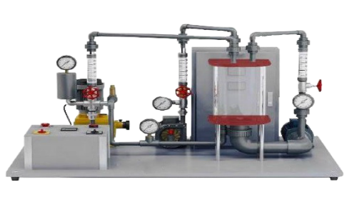
Multi Pump Trainer Unit
Order Code: 21224924.2.3
Category: General Lab Equipment II
Scope: The trainer kit should come as a single compact unit Computer Controlled Multi pump Testing Bench Unit with Real -time SCADA system: Unit designed to demonstrate the operating characteristics of several types of pumps. Anodized alu...
SPECIFICATION
Scope:
The trainer kit should come as a single compact unit
Computer Controlled Multi pump Testing Bench Unit with Real -time SCADA system:
- Unit designed to demonstrate the operating characteristics of several types of pumps.
- Anodized aluminum frame and panels made of painted steel.
- The unit includes wheels to facilitate its mobility.
- Main metallic elements made of stainless steel.
- Diagram in the front panel with distribution of the elements similar to the real one.
- Fully instrumented self-contained unit.
- The unit is mounted on a structure with a work surface covered by a plastic sheet.
Following types of pumps should be embedded in the compact unit
Rotodynamic Pumps
- Centrifugal Pump I
- Centrifugal Pump II in series and parallel
- Axial Flow Pump
- Turbine Pump or Peripheral Pump Positive Displacement Pump
- Gear Pump
- Flexible Impeller Pump
- Diaphragm pump
- Plunger Pump (Piston Pump)
1.Centrifugal Pump (1& II)
- Determination of the curve Q vs r.p.m. of the centrifugal pump.
- Determination of the curve H vs Q for different r.p.m. of the centrifugal pump.
- Determination of the mechanical power vs flow for different r.p.m. of the centrifugal pump.
- Determination of the curve η vs the flow for different r.p.m. of the centrifugal pump
- Determination of the map of a centrifugal pump.
- Coupling in series of two centrifugal pumps of different characteristics.
- Coupling in series of two centrifugal pumps with the same characteristics.
- Parallel coupling of two centrifugal pumps with similar characteristics & Parallel coupling of two centrifugal pumps of different characteristics
2. Axial Flow Pump
- Determination of the curve Q vs r.p.m. of the axial pump.
- Determination of the curve H vs Q for different r.p.m. of the axial pump.
- Determination of the mechanical power vs flow for different r.p.m. of the axial pump.
- Determination of the curve η vs the flow for different r.p.m. of the axial pump.
- Determination of the map of an axial pump.
3. Turbine Pump or Peripheral Pump
- Determination of the curve Q vs r.p.m. of the peripherical pump.
- Determination of the curve H vs Q for different r.p.m. of the peripherical pump.
- Determination of the mechanical power vs flow for different r.p.m. of the peripherical pump.
- Determination of the curve η vs the flow for different r.p.m. of the peripherical pump.
- Determination of the map of a peripherical pump.
4. Gear Pump
- Determination of the curve Q vs r.p.m. of the gear pump.
- Determination of the curve H vs Q for different r.p.m. of the gear pump.
- Determination of the mechanical power vs flow for different r.p.m. of the gear pump.
- Determination of the curve η vs the flow for different r.p.m. of the gear pump.
- Determination of the map of a gear pump.
5. Flexible Impeller Pump
- Determination of the curve Q vs r.p.m. of the flexible impeller pump.
- Determination of the curve H vs Q for different r.p.m. of the flexible impeller pump.
- Determination of the mechanical power vs flow for different r.p.m. of the flexible impeller pump.
- Determination of the curve η vs the flow for different r.p.m. of the flexible impeller pump.
- Determination of the map of a flexible impeller pump.
Diaphragm Pump
- Determination of the curve Q vs r.p.m. of the diaphragm pump. Determination of the curve H vs Q for different r.p.m. of the diaphragm pump.
- Determination of the mechanical power vs flow for different r.p.m. of the diaphragm pump.
- Determination of the curve η vs the flow for different r.p.m. of the diaphragm pump.
- Determination of the map of a diaphragm pump.
Plunger Pump
- Determination of the curve Q vs r.p.m. of the plunger pump.
- Determination of the curve H vs Q for different r.p.m. of the plunger pump.
- Determination of the mechanical power vs flow for different r.p.m. of the plunger pump.
- Determination of the curve η vs the flow for different r.p.m. of the plunger pump.
- Determination of the map of a plunger pump.
Layout :
- Length - 2.5 m or below
- Width - 1.5 m or below
- Height - 2 m or below
- Weight - Around 500kg
Technical specifications:
- Centrifugal Pump and Second Centrifugal Pump
- A brass-body
- Pedestal or of free axis type
- Stainless steel shaft.
- flow 80 l/min or above
- head 9m or above
- Efficiency is 35% or above
Gear Pump
- Corrosion-resistant bronze-bodied gear pump
- With stainless steel shafts
- Bronze helical gears
- Should quiet in operation
- flow 13.7 l/min or above
- head 40m or above
- Efficiency is 70% or above
Axial Flow Pump
- With propeller, which works in an acrylic casing with thin interstices between the propeller and the casing.
- flow 50 l/min or above
- head 1.8m or above
- Efficiency is 15% or above
Flexible Impeller pump
- Bronze pump head
- Stainless steel shaft and flexible impeller
- flow 60 l/ min at head of 20m or above
Turbine Pump or Peripheral Pump
- With a runner of straight blades inside an annular casing and an axis of activation on two lubricated ball bearings.
- Bronze pump body
- Stainless steel shaft
- flow 24 l/min or above
- head 20m or above
Diaphragm Pump
- flow 5.8 l/min at a maximum head of 30m or above
- Stainless steel wetted parts
Plunger Pump
- Stainless steel wetted parts
- flow 5.3 l/min at maximum head of 60m or above
Instrumentation and controls: All the services and instrumentation for determining the characteristic curves of eight different pumps at different speeds should be supplied For rotodynamic pumps:
- Pressure head vs flow
- Power absorbed vs flow
- Pump efficiency vs flow
For positive displacement pumps:
- Flow vs pressure head
- Power absorbed vs pressure head
- Volumetric efficiency vs pressure head
Computer Control +Data Acquisition+Data Management Software software should be included
- A Compatible computer (PC) should be supplied
- Processor: 7th Gen. Intel Core i5 - 7400 (6MB Cache) 3.0 GHz recommended
- 16GB DDR4 RAM recommended
- 1TB 5400 RPM SATA SSD recommended
- OS: Windows 10 (64bit)
- Keyboard /Mouse
- Ports (recommended specs)
- 4 x USB 3.0
- HDMI-out
- DisplayPort 1.2
- 2 x Thunderbolt 3 (supports Type-C, USB3.1, DisplayPort, PS)
- Gigabit Ethernet, audio out
- Display: 21.5” LED monitor is recommended Components
- Compatible power cord and adapter
- Necessary tool kits, supplementary parts
- Required calibration manuals should be supplied
- Assembly and Installation, Interface and Control Software, Starting-up, Safety, Maintenance, Calibration & Practices Manuals should be supplied
Enquiry Form
Related Product


Tesca specialize in doing turnkey projects that is fully operable when it is handed over to the project authority. Starting from inception to application training, Tesca provides the services as ONE source solution. Working side by side with government authorities and people across the World, we help countries to perform better. We support countries grow their economies, strengthen their education and health systems and improve financial management. We do this by providing consultancy & training in environment safety, education, health strengthening.
Category
Useful Links
Contact Us
International Sales:
 91-9829132777
91-9413330765
India Sales:
91-9588842361
2026 © All Rights Reserved.