
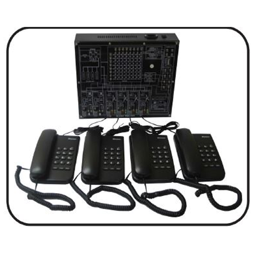
Pcm/Tdm Telephony Trainer
Order Code: 19203334.6A
Category: General Lab Equipment III
This module should have the theoretical study, supported by exercises. concerning telephony using multiplex with PCM-TDM coding It is equipped with all the functions of a telephone exchange used in a communication system 041 PSTN line Basi...
SPECIFICATION
- This module should have the theoretical study, supported by exercises. concerning telephony using multiplex with PCM-TDM coding It is equipped with all the functions of a telephone exchange used in a communication system 041 PSTN line
- Basics of telephony: Telephone and power. (Pulse/DTMF) dialing and communication Signals.
- User interface (SLIC): -El (Battery powered): telephone Set powered by the exchange. - O (Oven/014We PftateCtiOn). protection against over voltages from the line R (Ringing) 0:introl of ringing current - S (Supervision). detection Cl Off-hook handset and of mu m-freguency dialing pulses or tones - H (Hybrid) conversion from 2 to 4 wires and vice versa - T (Testing) level 01 signalsrharaclenstias Of line
- CODEC: channel Her 3110-340010 in transmission and reception - 64 kb/5 PCM encoding/decoding transmission and reception Time Slot assignment and frame insertion at 2041$ Hips (standard E I) Simultaneous communication of more users - analogue multiplex EDF! - digital multiplex PCM-T1311.1 - Digital switched matrix - CEPT interface and tlei83 coding Line interface Line signal conversion' unipolar-bipolat - I iming and exchange tones - Data transmission on switched line via 2 modules mod
- Operating modes - TOM E I Mime generabon — 32 PCM Channels -Digital exchange switching On line with FIDB3 Ceding Line simulator Assessment of service quality - Bidirectional link via 2 nxxitries mod - External loop on coaxial lint
- 4 User jacks for the connection of max 4 use N for PSTN Networks. Induding SI IC, COOEC. (Nodal Smith and I roe Interface
- Display of transmission and reception time slots and frames - Arunciai line simulator with controls of attenuation and noise generator - PC - interfaCeat)le control microprocessor. - Synchronization system for displaying time skits on oscilloscope LEDs of state indication Signaling Clock Loss. HER. Frame Sync. Multi-Frame SynC - Incoming calls - switch Hook detection -1.)11.11- binary code and Line signaling
- I interface for connection with supervision PC - I supervision software rot programming exchange operating parameters' it must be installed in I PC
- Power Supply Unit : 12 VdC - 0.5 A 24 Vac - 0.1 A
- Personal Computer With Operating system window latest version -Intel Core - Window 10 - AGB RAM - tilt HDD - Intel HD Graptucs 520 20- monitor
Enquiry Form
Related Product


Tesca specialize in doing turnkey projects that is fully operable when it is handed over to the project authority. Starting from inception to application training, Tesca provides the services as ONE source solution. Working side by side with government authorities and people across the World, we help countries to perform better. We support countries grow their economies, strengthen their education and health systems and improve financial management. We do this by providing consultancy & training in environment safety, education, health strengthening.
Category
Useful Links
Contact Us
International Sales:
 91-9829132777
91-9413330765
India Sales:
91-9588842361
2026 © All Rights Reserved.