
PLC Operated Electric Motor Controlling Trainer
Order Code: 21225210.12
Category: General Lab Equipment I
Training Program to be Performed: PLC architecture Instructions processing: the cycle concept Synchronous, asynchronous and priority cycles Performing times, cycle and reaction Boolean Algebra AWL, KOP, FUP, SCL, S7-GRAPH programming ...
SPECIFICATION
Training Program to be Performed:
- PLC architecture
- Instructions processing: the cycle concept
- Synchronous, asynchronous and priority cycles
- Performing times, cycle and reaction
- Boolean Algebra
- AWL, KOP, FUP, SCL, S7-GRAPH programming
- Combinational logic functions
- Sequential logic functions
- Addressing
- Timers & counters
- Clock generators
- Monostable and bistable circuits
- Algebra operation: addition, subtraction, multiplication
- BCD/binary conversions
- Binary/BCD conversions
- Structured programming techniques
- Basic and structured data
- Programming of functions, function blocks, data blocks
- Integrated functions of fast counting, frequency measurement, positioning
- Process interruptions management
- Industrial networks: Profinet and Profibus
- Programming and use of industrial operators panels
- Technical Specifications:
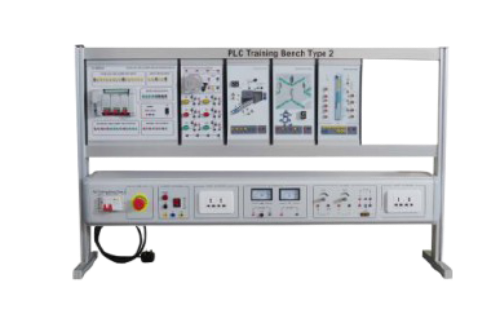
- Tabletop metal box with press-formed aluminium section structure
- Side handles , not protruding, for easy transport in the laboratory
- Front panel, in insulating material, with silk screen representation of the diagrams and inner components of the equipment
- 24 Vdc/3 A power supply for control of the digital inputs and outputs. With electronic protection against short-circuits and overloads.
- 24 Vac/3 A power supply relay outputs control with fuse protection against overloads
- 1 3 and 1/2-digit digital voltmeter for measurement of the voltage present across the inputs or the analog output 0.1 Vdc resolution.
- 1 Rotating switch for voltmeter input selection
- 4 analog inputs V/I: ±10 Vdc, ±20 mA
- 1 input for Pt 100 temperature probe
- 2 analog outputs V/I: ±10 Vdc, ±20 mA
- 4 Rotating potentiometers for setting up voltage analog references in the range 0..10 Vdc
- Inner voltage reference obtained via 24 Vdc inner stabilizer
- 24 Digital standard inputs of which 12 special for technologic functions (counting, frequency measurement max 60 kHz. Digital input simulator with permanent and pulse state switches
- Simulator block for testing the program during commissioning and operation, 16 digital inputs or 16 digital outputs or 8 digital inputs and 6 digital outputs
- 16 24 Vdc digital outputs
- Safety terminals, standard Ø 4 mm and Ø 2 mm for connection of the inputs and outputs to external devices.
- Digital outputs interfacing With 10 Aac/2 Adc relay, Transistor for fast applications
- PLC characteristics
- Power Supply: 24 Vdc
- Working memory: 192 kByte
- Load memory: 512 Kbyte with MMC
- Programming interface: RS-485
- Network interface: RS-485, Profinet, Profibus
- Communication: MPI (Multi Point Interface)
- Operating mode: Master/Slave
- Digital inputs: 24 at 24 Vdc; potential separation in groups of 4; protect. from polarity inversion. Bit, byte, word addressing
- Special digital inputs: 12 with technologic functions
- Input state display: green LED
- Digital outputs: 16 at 24 Vdc/0,5 A; galvanic separation from CPU in groups of 8; immunity against short-circuits.
- Bit, byte, word addressing
- Output state display: LED diodes
- Analog inputs: 4 voltage/current
- Temperature probe input: 1 for Pt100 probe
- A/D conversion resolution: 11 bit + sign
- Range of the analog input voltage: ±10 Vdc
- Range of the analog input current: ±20 mA
- Analog outputs: 2 voltage/current:
- D/A conversion resolution: 11 bit + sign
- Range of the analog output voltage: ±10 Vdc
- Range of the analog output current: ±20 mA
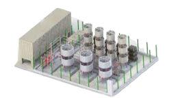
- This System Simulator consists of a panel that can be used as tabletop unit or mounted on vertical frame.
- It includes 12 inputs and 12 digital outputs connected via safety leads with plugs of Ø 4 mm.
- Two potentiometers enable to set two analog variables (0 - 10 V) used, for instance, to indicate the filling rate of a bin, the up and down movements of an elevator, etc.
- 6 instantaneous contacts held by switches and 6 LEDs of state indication are available on the fore panel.
- A bargraph display will show the level of a tank or the position of an elevator; 6 electric limit switches enable to monitor the minimum/maximum positions, as well as the intermediate positions.
Enquiry Form
Related Product

Tesca specialize in doing turnkey projects that is fully operable when it is handed over to the project authority. Starting from inception to application training, Tesca provides the services as ONE source solution. Working side by side with government authorities and people across the World, we help countries to perform better. We support countries grow their economies, strengthen their education and health systems and improve financial management. We do this by providing consultancy & training in environment safety, education, health strengthening.
Category
Useful Links
Contact Us
International Sales:
export@tesca.in
 91-9829132777
91-9413330765
India Sales:
indiasales@tesca.in
91-9588842361
2026 © All Rights Reserved.