
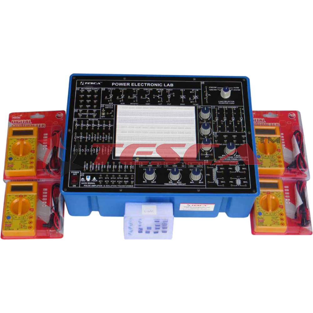
Power Electronics Control Board
Order Code: 22235697.2.12
Category: General Lab Equipment I
Power Electronics Lab is used to perform power electronics circuit experiments. It is very useful in power electronics laboratories for performing power experiments in colleges and universities. It is very for student to know about the character...
SPECIFICATION
Power Electronics Lab is used to perform power electronics circuit experiments. It is very useful in power electronics laboratories for performing power experiments in colleges and universities. It is very for student to know about the characteristics of power electronics devices and the applications of power devices. The applications or power devices are in alarm circuit, lamp flasher, rectifiers, choppers, invertors. It is also used for commutation circuits.
The Equipment is Useful for Students at level in engineering / technical institutes (EC & Telecom) Technical training centers in communication organizations, R&D personal and practicing engineering in research labs and industry.
Technical Specifications:
- DC Power Supply on Board
- ± 5V at 100mA
- ± 12V at 150mA
- ± 15V at 50mA
- ± 35V at 50mA
- AC Power Supply on Board :
- 18V - 0V - 18V at 50mA
- 15V - 0V - 15V at 50mA
- Triggering Circuit on Board : 5 gate signal output
- Frequency range : 40Hz to 900Hz Variable
- Amplitude :
- 12V
- PWM control of G1,G2,G3 and G4 Duty
- cycle control of “Gate” Signal is 0 to 100%
- Single Phase Rectifier : Firing angle control 0°-180° variables
- Firing Circuit on Board : Four gate signal output with isolation
- SCR Assembly : 4 SCRs 2P4M, 600V,2A
- Power Devices : IGBT-G4BC20S, MOSFET-IRF540, UJT-2N2646, DIAC-DB3, TRIAC-BT136, PUT-2N6027
- Circuit Components On Board :
- Capacitor 0.01uF, 0.047uF , 0.1uF, 0.33uF, 1uF/63V(4Nos.) 2.2uF/50V
- Diode 1N4007 (8Nos.)
- Zener Diode 9V (1Nos. )
- Inductors 10mH, (1Nos.), 68mH (2Nos.)
- Load Resistance 120E, 270E, 1K, 2K2, each 5W
- Resistance on Board (½ W) 22E/5W, 100E/2W, 220E/2W
- Resistance on Board(1/4W) 10K (3Nos.), 22K,33K,47K,
- Potentio Meter 4K7(2Mos.), 1M(1Nos.)
- Pulse Transformer on Board : 2 Nos. PT4502, 1:1 and one is PT4503 1:1:1
- Toggle Switch : SPST (1Nos.)
- Power Requirements : 220V ±10%, 50Hz
Experiments On Board Using Breadboard:
- To study the characteristics of SCR and plot its V-I Characteristics.
- To study the Gate control characteristics of SCR and It's graph.
- To study the characteristics of UGT and calculate interbase resistance and intrinsic standoff ratio.
- To study the characteristics of MOSFET.
- To study the characteristics of IGBT.
- To study the characteristics of DIAC and plot its V-I Characteristics curve.
- To study the V-I characteristics of TRIAC.
- To study the characteristics of PUT.
- To study of class B commutation circuit.
- To study of class C commutation circuit.
- To study of class D commutation circuit.
- To study of class F commutation circuit.
- To study the Resistor Triggering circuit.
- To study the Resistor-Capacitor Triggering Circuit (Half wave).
- To study the Resistor-Capacitor Triggering Circuit (Full wave).
- To study the triggering of SCR using UJT.
- To study the Triggering of SCR using 555 IC.
- To study the Triggering of SCR using Op-Amp 74I IC.
- To study of the ramp and pedestal triggering using anti-parallel SCR in AC load.
- To study of the UJT relaxation oscillator.
- To study of the voltage commutated chopper.
- To study of the Bedford inverter.
- To study of the single phase PWM inverter using MOSFET.
- To study of the single phase PWM inverter using IGBT.
- To study the half-wave controlled rectifier with resistive load
- To study the half wave controlled rectifier with RL load.
- To study the full-wave controlled rectifier (mid-point configuration) with resistive load.
- To study the full-wave controlled rectifier (mid point configuration) with RL load.
- To study the fully controlled bridge rectifier with resistive load.
- To study the fully controlled bridge rectifier with RL load
Enquiry Form
Related Product


Tesca specialize in doing turnkey projects that is fully operable when it is handed over to the project authority. Starting from inception to application training, Tesca provides the services as ONE source solution. Working side by side with government authorities and people across the World, we help countries to perform better. We support countries grow their economies, strengthen their education and health systems and improve financial management. We do this by providing consultancy & training in environment safety, education, health strengthening.
Category
Useful Links
Contact Us
International Sales:
export@tesca.in
 91-9829132777
91-9413330765
India Sales:
indiasales@tesca.in
91-9588842361
2026 © All Rights Reserved.