
Power Electronics Training System* Laboratory

Order Code: 23246810.2
Category: General Lab Equipment II
Minimum required didactic content: Basic knowledge of diodes, thyristors and triacs, Rectification Control principles: phase control, full-wave control, burst firing control, pulse pattern control, rectifier operation, inverter operation M1, M2, M3, ...
SPECIFICATION
Minimum required didactic content: Basic knowledge of diodes, thyristors and triacs, Rectification Control principles: phase control, full-wave control, burst firing control, pulse pattern control, rectifier operation, inverter operation M1, M2, M3, B2, B6, M1C, M2C, M3C, B2C, B6C, B2HA, B2HK, B2HZ, B6C, B6HA, B6HK, W1C and W3C circuits Resistive and inductive loads, Load characteristics and operating diagrams,
Protective circuits Computer-based measurement, Frequency analysis and analysis of harmonics Basic knowledge of IGBTs Control principles: pulse-width modulation, DC choppers in 1-, 2- and 4- quadrant operation Modulation of low-frequency AC voltages using pulse width modulation Circuits: step-down controller, H-bridge, inverter, Resistive and inductive loads Protective circuits, DC link circuits, freewheeling,
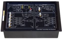
Control characteristics and operating diagrams Interpolation nodes, clock frequency, ripple Computer-based measurement, Frequency analysis and analysis of harmonics Complied 23246810.2 Closed-loop speed control in 1 and 4 quadrant operation with and without secondary current control Open-loop speed control in 1-quadrant operation with IGBT Open-loop speed control in 4-quadrant operation with IGBT Closed-loop speed control, closed-loop current control, cascade control, adaptive control Computer-assisted controlled-system and controller analysis, setting parameter P-, PI-, PID control Controller optimization Includes at least the following DIN A4 modules with the following characteristics: All modules are supplied as a DIN A4 high didactic panel with 4mm secure connection plugs and color printing of wiring diagrams, photos etc. 1x Line-commutated converter circuits Control unit with 6 power diodes, 12 thyristors and a triac Control and measuring unit based on digital signal processor Integrated measurement of 6 different currents and 6 voltages Integrated controller function for building closed-loop controlled drives USB interface, Input for incremental sensor, Analog input Supply voltage: 3 x 47 V... 400 V, 50...60 Hz, Maximum output power: 1 kVA Protection against incorrect operation Measurement of changes in output current and voltage over time with graphic display of timing diagrams featuring up to 20 channels Calculation and graphic display of changes in input and output power over time Calculation of RMS values, mean values and AC components of current and voltage as well as apparent power, active power (DC and AC components), reactive power and form factor Automatic recording of control characteristic with graphic display Graphic display of dependencies of all calculated values on phase control angle Three-dimensional vector display of output power Analysis of signals using FFT (Fast Fourier Transformation) Synthesis of signals using step-by-step combinations of individual sine and cosine components. Animation, i.e. step-by-step addition of individual oscillation components to demonstrate how signals are put together Export function for graphics and measurements 1x Self-commutated power converter circuits Control unit with 6-pulse IGBT AC inverter Control and measuring unit based on digital signal processor Integrated measurement of 3 different currents and 6 voltages Electronic monitoring and cut-off for excess voltage and overloading Integrated controller function for building variable speed drives Interface for connection to MATLAB Selectable PWM frequencies USB interface, Input for incremental sensor, Analog input, Integrated brake chopper Supply voltage: 3 x 47 V... 400 V, 50...60 Hz, Maximum output power: 1 kVA Measurement of changes in output current and voltage over time with graphic display of timing diagrams featuring up to 20 channels Calculation and graphic display of changes in input and output power over time Calculation of RMS values, mean values and AC components of current and voltage as well as apparent power, active power (DC and AC components), reactive power and form factor Automatic recording of control characteristic with graphic display Graphic display of dependencies of all calculated values on duty cycle Three-dimensional vector display of output power Analysis of signals using FFT (Fast Fourier Transformation) Synthesis of signals using step-by-step combinations of individual sine and cosine components. Animation, i.e. step-by-step addition of individual oscillation components to demonstrate how signals are put together Export function for graphics and measurements 1x Three-phase isolating transformer, 300 VA Input voltage: 3x 400V, 50Hz via CEE plug, Output voltage 1: 3 x 94 V with center tap for 47 V Output voltage 2: 3 x 400 V Protection via 2 separate thermo-magnetic circuit breakers with under voltage trip Power: 300 VA, Thermo-magnetic circuit breaker 1x RL load set with self-resetting overload protection and indicators for current magnitude and direction 1x Didactic RMS voltage/current/power measuring instrument system TRMS Multimeter / Power meter / Power factor meter Separate input for voltage and current / Electrically indestructible up to 20 A/600 V 5.7" color touch screen for the display of 1 to 4 simultaneous digital and analog values Galvanically isolated USB interface with many virtual instruments such as oscilloscope, power meter, voltage/current/power plotter (software included) 1x Servo motor brake system to perform experiments on the machines Speed or torque control without and with PC / special network synchronization mode 5.7" color touch screen / simultaneous display of mechanical (speed, torque, power) and electrical values (voltage, current, apparent/active/reactive power, cos phi, power factor) Galvanically isolated USB interface / software for measuring mechanical and electrical characteristics Simulation of industrial loads for testing electrical machines (calender, pump, inertia mass, compressor, time-variable load, etc.) with max. torque 10 Nm / speed 4000min-1 Analysis of the motor curve / operating point / characteristics over time with recording of the measured values including load-dependent starting current. Integrated interface for reading electronic nameplates of ESD motor samples Coupling sleeve and guard / Integrated LED protective cover / Motor temperature monitoring Includes at least the following electrical machines with the following minimum characteristics: Industrial type machines mounted on chassis with anti-vibration system Coupling with single sleeve without tools on standard table between machine and brake Winding diagram printed on a uniform size panel on the front side of approx. 170 x 140mm Machine terminal board with 4mm safety plugs, always on the front panel on the learner's side. Temperature sensor against thermal overload integrated in each machine ESD electronic chips for automatic transmission of machine data to the brake test bench 1x DC multi-circuit, compound wound machine 2000trs/min, 220V, 0,2kW Can be used as shunt, series or compound motor/generator 1x Tachogenerator 1 V/1000 rpm, 0.3 kW All accessories necessary for proper operation must be provided, with at least the following: 1x Coupling guard 0.3kW with LED lighting 1x Rubber coupling sleeve, 0.3kW 1x Mobile aluminium experiment stand, 3 levels, 6 x earthed sockets 30-mm table top made of highly compressed, multi-layer chipboard, Resistant to heat and many chemicals Frame with solid impact-resistant protective edging made of 3mm thick RAL 7047 coloured plastic Coating and adhesive are PVC free Power strip with 6 outlet sockets mounted underneath the table top, lead and earthed plug 2 extruded aluminium profiles with multiple grooves 1800 x 120 x 40 mm (WxHxD) 8 equally sized grooves in extruded aluminium profiles (3 on each side and 1 each on the front and back) Table frame made of tough combination of rectangular tubing around the full perimeter PC and Monitor holder 1x Power supply for tables (2x CEE 16A, 230V, circuit breaker) 1x Interactive multimedia courses Interactive experiment setups with animation Measured values and diagrams can be stored in the experiment instructions per drag and drop Direct link to instruments/measurement and test software from the experiment instructions Includes questions with feedback and evaluation logic for progress monitoring Documents can be printed out for hardcopy of experiment instructions including solutions 1x 4mm safety measuring cable set and 19/4mm safety plug set 1x Standard branded PC with 24'' screen, adapted keyboard, Windows 10 or 11, UPS, spare battery Technical Clauses:
The bidder must present a manufacturers authorization
Training manual for the items in form of an interactive software course
Software packages needed for conducting experiment using these items
The supplier must provide Minimumu 3 days of training to max. 15 trainers
Enquiry Form
Related Product


Tesca specialize in doing turnkey projects that is fully operable when it is handed over to the project authority. Starting from inception to application training, Tesca provides the services as ONE source solution. Working side by side with government authorities and people across the World, we help countries to perform better. We support countries grow their economies, strengthen their education and health systems and improve financial management. We do this by providing consultancy & training in environment safety, education, health strengthening.
Category
Useful Links
Contact Us
International Sales:
 91-9829132777
91-9413330765
India Sales:
91-9588842361
2026 © All Rights Reserved.