
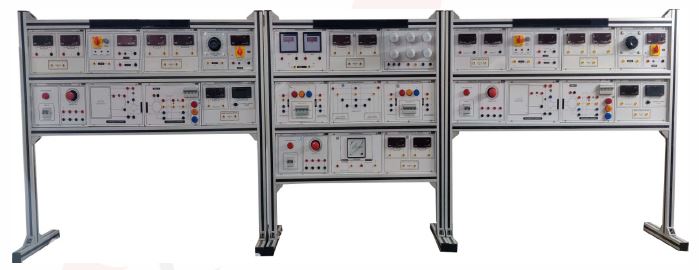
PROTECTIVE RELAYING SYSTEM
SPECIFICATION
PROTECTIVE RELAYING SYSTEM
TECHNICAL SPECIFICATION
- Power System Protection Laboratory Workbenches
1. PURPOSE
- To procure a modular protection laboratory workbench capable of delivering practical, hands-on training in power system protection for:
- Synchronous generators
- Power transformers
- Transmission lines
- Protection coordination and grading
- Relay parameterization and performance evaluation
- The system shall allow controlled simulation of normal operating conditions, abnormal system conditions, and power system faults.
2. GENERAL REQUIREMENTS
- The offered system shall be:
- A fully integrated laboratory workbench or modular training platform
- Designed for three-phase operation at 400 V (50/60 Hz)
- Digital relays
- Suitable for safe indoor laboratory use
- Electrically protected against overload and short-circuit
- Designed with safety laboratory connectors (minimum CAT II rating)
- • Compliant with applicable IEC/EN safety standards
- • Expandable for future additions
- The system shall support repeated fault simulation without equipment damage.
3. FUNCTIONAL CAPABILITIES
- The target is to procure TWO complete workbenches. Each workbench shall enable controlled experimentation in the following domains.
4. GENERATOR PROTECTION TRAINING CAPABILITIES
4.1 Generator Operation
- Perform manual and automatic synchronization
- Control and observe active and reactive power
- Observe power factor variation
- Study generator behavior under balanced and unbalanced loading
- Operate the generator in motoring and generating modes
4.2 Fault Simulation
- The system shall allow simulation of:
- Single-phase faults
- Phase-to-phase faults
- Three-phase faults
- Earth faults
- Internal and external faults relative to protection zone
- Faults shall be safely generated and cleared.
4.3 Protection Behaviour Analysis
- The system shall enable determination of:
- Pick-up (operating) current/voltage
- Tripping time
- Reset ratio
- Release time
- Characteristic curves
- Operation under unbalanced conditions
- Reverse power conditions
- Over/under voltage conditions
- Over/under frequency conditions
- Thermal effects (simulated acceptable)
- Students shall be able to:
- Compare measured values with set values
- Analyze misoperation due to incorrect se????ngs
- Study zone selectivity
5. TRANSFORMER PROTECTION TRAINING CAPABILITIES
5.1 Transformer Operation Studies
- Study of transformer energization
- Observation of inrush phenomena
- Study of vector group effects
- Study of CT ratio and polarity influence
5.2 Fault Conditions
- The system shall allow simulation of:
- Internal faults
- External faults
- Earth faults
- Inrush conditions
- Incorrect current transformer configuration
5.3 Protection Evaluation
- Students shall be able to:
- Observe discrimination between inrush and internal faults
- Measure differential quantities
- Design of % differential relays
- Determine tripping time
- Study grading with upstream and downstream protection
- Configure protection parameters and verify performance
6. TRANSMISSION LINE PROTECTION CAPABILITIES
- The workbench shall include an adjustable transmission line simulation environment capable of:
- Representing different line lengths
- Representing different fault locations
- Adjustable impedance conditions
- Simulating forward and reverse faults
- The system shall allow:
- Study of zone-based protection
- Determination of reach settings
- Study of fault resistance influence
- Testing faults inside and outside protection zone
- Evaluation of backup protection
7. OVERCURRENT AND DIRECTIONAL PROTECTION STUDIES
- The system shall allow students to:
- Implement time overcurrent protection
- Select inverse characteristics
- Set time multipliers
- Determine coordination margins
- Prepare grading schedules
- Study directional elements
- Study forward and reverse power flow
- Study interaction between primary and backup protection
- The system shall allow verification of:
- Selectivity
- Sensitivity
- Speed
- Stability
8. MEASUREMENT AND PERFORMANCE ANALYSIS CAPABILITIES
- The laboratory workbench shall provide facilities to:
- Measure three-phase voltage and current
- Measure active, reactive and apparent power
- Measure power factor
- Measure fault current magnitude
- Record tripping times with millisecond resolution
- Capture event sequences
- Export measured data for analysis
- Phasor measurement units
- The system shall allow:
- Comparison between theoretical and measured values
- Ploting of protection characteristics
- Analysis of operating vs restraint quantities
- Disturbance recording
9. PARAMETERIZATION AND CONTROL
- The system shall support:
- Digital configuration of protection parameters
- Adjustment of operating thresholds
- Adjustment of time delays
- Storage and recall of multiple settings
- User access control
- Reset and recovery after trip
10. SCADA AND VISUALIZATION REQUIREMENTS
- The system shall include supervisory software capable of:
- Real-time single-line diagram visualization
- Display of measured electrical parameters
- Indication of protection status
- Event logging
- Fault recording
- Data export for reporting
- Printing of experiment results
- The interface shall allow:
- Configuration of protection parameters
- Reseting and acknowledgment of alarms
- Monitoring of system state
11. EDUCATIONAL SOFTWARE REQUIREMENTS
- The laboratory shall include structured educational content with:
- Guided experiment procedures
- Step-by-step setup instructions
- Embedded diagrams
- Data entry capability
- Automatic evaluation and feedback
- Knowledge assessment modules
- Printable documentation
- The system shall support instructor-led and self-learning modes.
12. SAFETY REQUIREMENTS
- The workbench shall include:
- Overcurrent protection
- Short-circuit protection
- Emergency stop
- Safe fault injection method
- Insulated terminals
- Clearly identified earthing
- Protection against accidental contact with rotating parts
- Visual fault indication
- The system must prevent hazardous energy exposure during experiments.
13. PERFORMANCE REQUIREMENTS
- The system shall:
- Support continuous laboratory use
- Allow repeated fault testing without degradation
- Maintain measurement accuracy within ±2% or better
- Provide tripping time measurement accuracy within ±5 ms or better
14. DELIVERY AND COMMISSIONING
- The supplier shall provide:
- Installation and commissioning
- Functional demonstration of all experiment capabilities
- Instructor training
- Complete documentation
- Wiring diagrams
- Example protection setings
- Installation and commissioning
- The vendor needs to include installation, testing and commissioning of the whole set up on the site (EE Lab)
Enquiry Form
Related Product

Tesca specialize in doing turnkey projects that is fully operable when it is handed over to the project authority. Starting from inception to application training, Tesca provides the services as ONE source solution. Working side by side with government authorities and people across the World, we help countries to perform better. We support countries grow their economies, strengthen their education and health systems and improve financial management. We do this by providing consultancy & training in environment safety, education, health strengthening.
Category
Useful Links
Contact Us
International Sales:
 91-9829132777
91-9413330765
India Sales:
91-9588842361
2026 © All Rights Reserved.